The journey of capacitors began in the 18th century. The first device capable of storing electric charge was the Leyden jar, invented independently by Ewald von Kleist and Pieter van Musschenbroek around 1745-46. These jars were essentially glass bottles partially filled with water and sealed with a metal wire passing through the cork top. The wire acted as one electrode and the hand holding the jar acted as the other.
Over time, the design of capacitors evolved significantly. The Leyden jar was the precursor to more sophisticated capacitors with better materials and designs. The basic principle, however, remained the same: capacitors store electrical energy in an electric field created between two conductors separated by an insulator (or dielectric).
Today, capacitors come in various shapes and sizes, tailored for specific needs. They are made with materials that allow them to store more charge, withstand higher voltages, and fit into increasingly compact electronic devices. The dielectric can be air, paper, plastic, ceramic, or even a vacuum, each with its properties and applications.
The capacitor in an AC Circuit
When we apply an AC voltage to a capacitor, the capacitor doesn’t just charge up and stay charged as it would with a direct current (DC). Instead, it charges and discharges in a cycle, in rhythm with the AC voltage. This happens because AC voltage is not constant; it varies sinusoidally with time.
Imagine you’re at a playground, and there’s a seesaw. Now, think of the seesaw going up and down in a regular rhythm. This up-and-down motion is similar to how alternating current (AC) works. It’s a current that changes direction periodically, just like the seesaw’s motion.
Now, let’s introduce a capacitor into this scenario. A capacitor is like a storage tank for electric charge, but it has a unique property: it can only store charge up to a certain limit before it has to release it.
When we connect a capacitor to an AC circuit, something interesting happens. As the AC voltage increases, the capacitor starts charging, much like filling up our imaginary tank. When the voltage decreases, the capacitor discharges, just like emptying the tank.
Here’s the cool part: the capacitor charges and discharges in sync with the AC voltage’s rise and fall. This means that the charge on the capacitor is constantly changing, and so is the current in the circuit.
Let’s look at the math behind this process. If we apply an AC voltage that changes with time, represented by
\(\displaystyle \) V(t) = V_m \sin(\omega t) $
- Vm is the maximum voltage,
- ω is the angular frequency,
- t is time,
the capacitor’s charge Q also changes with time, since \(\displaystyle Q = C \cdot V \) and $$ C $$ is the capacitance of the capacitor.
The current $$ I $$, which is the rate of change of charge, is given by
\(\displaystyle I = \frac{dQ}{dt} \)
For a capacitor in an AC circuit, this current leads the voltage by a phase angle of 90∘, which means the current reaches its peak before the voltage does.
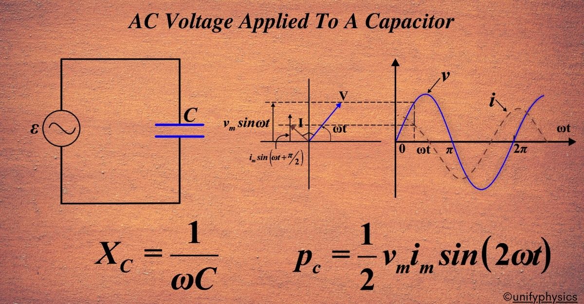
Capacitive Reactance: There’s a term we use to describe how much a capacitor resists the change in current: capacitive reactance (XC). It’s given by the formula
\(\displaystyle X_C = \frac{1}{\omega C} \).
This tells us that the capacitive reactance decreases as the frequency of the AC voltage increases. In simpler terms, the higher the frequency, the easier it is for the current to flow through the capacitor.
In an AC circuit, a capacitor acts like a dance partner to the alternating voltage, following its lead and changing its charge in harmony. It’s this beautiful synchronization that allows capacitors to play a crucial role in electronics, from filtering out unwanted noise to helping regulate the power supply.
Derivation: A capacitor is a passive electronic device with two terminals that can store electrical energy in an electric field. When an alternating current (AC) voltage is applied across a capacitor, the behavior is different from that in a direct current (DC) circuit.
In a DC circuit, when a capacitor is connected to a voltage source, the current will flow for a short time required to charge the capacitor. After this short interval, the current stops flowing.
However, in an AC circuit, the voltage across the capacitor continuously changes in a sinusoidal manner. This leads to the capacitor continuously charging and discharging. As a result, there is a continuous flow of current in the circuit.
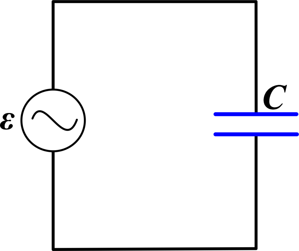
Let’s consider an AC voltage source applied across a capacitor. The potential difference or the AC voltage can be given as:
\(\displaystyle\boldsymbol{ v = v_m \sin(\omega t)}\)
where vm is the amplitude of the oscillating potential difference and ω is the angular frequency.
Also Read: AC Voltage Applied To An Inductor
The charge q on the capacitor is given by q = Cv, where C is the capacitance.
According to Kirchhoff’s rule, we can write from the above circuit:
\(\displaystyle v_m \sin(\omega t) = \frac{q}{C}\)
The current (i) through the circuit can be calculated using the relation \(\displaystyle i = \frac{dq}{dt}\). This gives us:
\(\displaystyle i = \frac{d(v_m C \sin(\omega t))}{dt} = \omega C v_m \cos(\omega t)\)
Using the relation \(\displaystyle\cos(\omega t) = \sin(\omega t + \frac{\pi}{2})\), we get:
\(\displaystyle i = i_m \sin(\omega t + \frac{\pi}{2})\)
where the amplitude of the current im is given by \(\displaystyle i_m = \omega C v_m\).
Here, we can see that the term \(\displaystyle\boldsymbol{\frac{1}{\omega C}}\) is equivalent to the resistance of this device and is termed as the capacitive reactance, denoted by XC. Thus, we can say that the amplitude of the current in this circuit is given as:
\(\displaystyle i_m = \frac{v_m}{X_C}\)
where, \(\displaystyle\boldsymbol{ X_C = \frac{1}{\omega C}}\).
The capacitive reactance restricts the passage of current in a purely capacitive circuit in the same way as resistance hinders the passage of current in a purely resistive circuit. It’s important to note that the capacitive reactance is inversely proportional to the frequency and the capacitance.
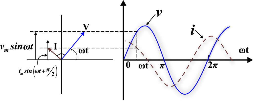
Graph of v and i versus ωt.
A comparison of Eq. i={{i}_{m}}\sin \left( {\omega t+\frac{\pi }{2}} \right)$ with the equation of source voltage, Eq. $$v = v_m \sin(\omega t)$$ shows that the current is π/2 ahead of voltage. The figure shows the phasor diagram at an instant t_1. Here the current phasor I is π/2 ahead of the voltage phasor V as they rotate counterclockwise. The figure shows the variation of voltage and current with time. We see that the current reaches its maximum value earlier than the voltage by one-fourth of a period.
Instantaneous Power
In an AC circuit with a capacitor, the current (i) and voltage (v) are related as follows:
\(\displaystyle i = i_m \sin(\omega t + \frac{\pi}{2})\)
\(\displaystyle v = v_m \sin(\omega t)\)
Here, im is the peak current, vm is the peak voltage, ω is the angular frequency, and t is time. The term \(\displaystyle\frac{\pi}{2}\) indicates that the current leads the voltage by a phase difference of \(\displaystyle\frac{\pi}{2}\) radians, or 90 degrees.
The instantaneous power (P) in an AC circuit is given by the product of the instantaneous voltage and current:
\(\displaystyle P = vi = v_m i_m \sin(\omega t) \sin(\omega t + \frac{\pi}{2})\)
However, the product of two sinusoidal functions can be rewritten using the trigonometric identity for the product of sines:
\(\displaystyle\sin(A)\sin(B) = \frac{1}{2}[\cos(A-B) – \cos(A+B)]\)
Applying this identity to the power equation gives:
\(\displaystyle P = \frac{1}{2} v_m i_m [\cos(\frac{\pi}{2}) – \cos(2\omega t + \frac{\pi}{2})]\)
Since \(\displaystyle\cos(\frac{\pi}{2}) = 0\), the equation simplifies to:
\(\displaystyle P = -\frac{1}{2} v_m i_m \cos(2\omega t + \frac{\pi}{2})\)
This equation shows that the instantaneous power oscillates at twice the frequency of the voltage and current, and its average value over a cycle is zero. This is because the capacitor stores energy in its electric field during one half of the cycle and returns it to the circuit during the other half. As a result, the net energy supplied to the capacitor over a complete cycle is zero.
However, this is not the standard form of the equation. We want to convert the above equation to the standard form of the equation. To do this, we can use the trigonometric identity that relates cosine and sine:
\(\displaystyle\cos(\theta + \frac{\pi}{2}) = -\sin(\theta)\)
Applying this identity to our power equation gives:
\(\displaystyle p_C = -\frac{1}{2} v_m i_m (-\sin(2\omega t))\)
Simplifying the equation gives the standard form of the equation for instantaneous power across a capacitor:
\(\displaystyle\boldsymbol{ p_C = \frac{1}{2} v_m i_m \sin(2\omega t)}\)
This equation shows that the instantaneous power also oscillates with time and has a frequency double that of the source frequency. The negative sign in the previous equation was due to the phase difference of \(\displaystyle\frac{\pi}{2}\) between the current and voltage. When we take that into account, we get the standard form of the equation.
The average power over a complete cycle is given by:
\(\displaystyle\langle p_C \rangle = \frac{1}{2} v_m i_m \langle \sin(2\omega t) \rangle\)
Since the average value of \(\displaystyle\sin(2\omega t)\) over a complete cycle is zero, the average power supplied to the capacitor over a complete cycle is zero. This is because the capacitor stores energy in its electric field during one half of the cycle and returns it to the circuit during the other half. As a result, the net energy supplied to the capacitor over a complete cycle is zero.
AC Biasing?
When an alternating current (AC) voltage is applied to a capacitor, the capacitor experiences a cycle of charging and discharging. This is because a capacitor has the ability to store electrical energy in an electric field.
During the positive half cycle of the AC voltage, the capacitor charges up, storing energy. As the AC voltage decreases and becomes negative, the capacitor begins to discharge, releasing the stored energy.
This continuous process of charging and discharging creates a current flow in and out of the capacitor at a regular rate, which is dependent on the frequency of the AC supply. This is why capacitors are often used in AC circuits to filter or regulate the flow of current.
AC biasing in a capacitor results in a continuous cycle of charging and discharging, creating a current flow that corresponds to the frequency of the AC voltage.
Also Read: AC Voltage Applied to a Series LCR Circuit
Solved Examples
Problem 1: An AC voltage of (\(\displaystyle V(t) = 100 \sin(100\pi t) \)) is applied across a capacitor of (50 µF). Calculate the RMS value of the current through the capacitor.
Solution: Given:
- (\(\displaystyle V(t) = 100 \sin(100\pi t) \))
- (\(\displaystyle C = 50 \mu F = 50 \times 10^{-6} \, F \))
The voltage is given by:
\(\displaystyle V(t) = V_0 \sin(\omega t) \)
where (V0 = 100 V) and (\(\displaystyle \omega = 100\pi \, \text{rad/s} \)).
The current through the capacitor is:
\(\displaystyle I(t) = C \frac{dV(t)}{dt} \)
\(\displaystyle I(t) = C \frac{d}{dt} (100 \sin(100\pi t)) \)
\(\displaystyle I(t) = 50 \times 10^{-6} \cdot 100 \cdot 100\pi \cos(100\pi t) \)
\(\displaystyle I(t) = 0.005 \cdot \pi \cos(100\pi t) \)
\(\displaystyle I(t) = 0.5\pi \cos(100\pi t) \, \text{A} \)
The RMS value of the current is:
\(\displaystyle I_{\text{RMS}} = \frac{I_0}{\sqrt{2}} \)
where (I0 = 0.5¶).
\(\displaystyle I_{\text{RMS}} = \frac{0.5\pi}{\sqrt{2}} \)
\(\displaystyle I_{\text{RMS}} = \frac{0.5\pi}{1.414} \)
\(\displaystyle I_{\text{RMS}} \approx 1.11 \, \text{A} \)
The RMS value of the current through the capacitor is (1.11 A).
Problem 2: An AC voltage source of (230 V) at a frequency of (50 Hz) is applied to a capacitor of (100 µF). Calculate the capacitive reactance and the current through the capacitor.
Solution: Given:
- (V = 230 V)
- (f = 50 Hz)
- (\(\displaystyle C = 100 \mu F = 100 \times 10^{-6} \, F \))
Capacitive reactance (XC) is given by:
\(\displaystyle X_C = \frac{1}{2\pi f C} \)
\(\displaystyle X_C = \frac{1}{2\pi \cdot 50 \cdot 100 \times 10^{-6}} \)
\(\displaystyle X_C = \frac{1}{2\pi \cdot 5 \times 10^{-3}} \)
\(\displaystyle X_C = \frac{1}{0.01\pi} \)
\(\displaystyle X_C \approx 31.83 \, \Omega \)
Current through the capacitor:
\(\displaystyle I = \frac{V}{X_C} \)
\(\displaystyle I = \frac{230}{31.83} \)
\(\displaystyle I \approx 7.23 \, \text{A} \)
The capacitive reactance is (31.83 Ω ) and the current through the capacitor is (7.23 A).
Problem 3: An AC voltage (\(\displaystyle V(t) = 120 \cos(200\pi t) \)) is applied to a capacitor of (20 µF). Determine the phase difference between the voltage and current.
Solution: Given:
- (\(\displaystyle V(t) = 120 \cos(200\pi t) \))
- (\(\displaystyle C = 20 \mu F = 20 \times 10^{-6} \, F \))
For a capacitor, the current leads the voltage by (90∘) (or (\(\displaystyle \pi/2 \)) radians). The phase difference between the voltage and current is (90∘) (current leads the voltage).
Problem 4: An AC voltage source (\(\displaystyle V(t) = 50 \sin(314t) \)) is connected across a capacitor of (10 µF ). Calculate the power dissipated in the capacitor.
Solution: Given:
- (\(\displaystyle V(t) = 50 \sin(314t) \))
- (\(\displaystyle C = 10 \mu F = 10 \times 10^{-6} \, F\) )
For an ideal capacitor, the power dissipated is zero because the current and voltage are ( 90∘) out of phase, leading to no net power transfer over a complete cycle. The power dissipated in the capacitor is (0 W).
Problem 5: A capacitor of (50 µF ) is connected to an AC voltage source with peak voltage (220 V). Calculate the maximum energy stored in the capacitor.
Solution: Given:
- (\(\displaystyle C = 50 \mu F = 50 \times 10^{-6} \, F \))
- (V0 = 220 V)
The energy stored in a capacitor is given by:
\(\displaystyle U = \frac{1}{2} C V_0^2 \)
\(\displaystyle U = \frac{1}{2} \times 50 \times 10^{-6} \times (220)^2 \)
\(\displaystyle U = \frac{1}{2} \times 50 \times 10^{-6} \times 48400 \)
\(\displaystyle U = 25 \times 10^{-6} \times 48400 \)
\(\displaystyle U = 1.21 \, \text{J} \)
The maximum energy stored in the capacitor is (1.21 J).
Problem 6: An AC voltage (\(\displaystyle V(t) = 100 \cos(120\pi t) \)) is applied to a capacitor of (25 µF). Calculate the voltage across the capacitor at (t = 1 ms).
Solution: Given:
- (\(\displaystyle V(t) = 100 \cos(120\pi t) \))
- (\(\displaystyle C = 25 \mu F = 25 \times 10^{-6} \, F \))
- (\(\displaystyle t = 1 \, \text{ms} = 1 \times 10^{-3} \, \text{s} \))
The voltage across the capacitor at (t = 1 ms):
\(\displaystyle V(1 \times 10^{-3}) = 100 \cos(120\pi \times 1 \times 10^{-3}) \)
\(\displaystyle V(1 \times 10^{-3}) = 100 \cos(0.12\pi) \)
\(\displaystyle V(1 \times 10^{-3}) = 100 \cos(21.6^\circ) \)
\(\displaystyle V(1 \times 10^{-3}) \approx 100 \cdot 0.928 \)
\(\displaystyle V(1 \times 10^{-3}) \approx 92.8 \, \text{V} \)
The voltage across the capacitor at (t = 1 ms) is (92.8 V).
FAQs
What happens when AC voltage is applied to a capacitor?
When AC voltage is applied to a capacitor, the capacitor charges and discharges continuously in response to the alternating current. This causes the current to lead the voltage by 90 degrees.
How does a capacitor react to a sinusoidal AC voltage?
A capacitor allows the AC current to flow through it by constantly charging and discharging. This process creates a phase shift where the current leads the voltage by 90 degrees.
Why does the current lead the voltage in an AC circuit with a capacitor?
The current leads the voltage in an AC circuit with a capacitor because the capacitor starts charging as soon as the voltage is applied, creating an immediate current flow. As the voltage across the capacitor increases, the rate of charge decreases, leading to a phase shift where the current reaches its maximum before the voltage does.
When AC voltage is applied, what is the phase relationship between voltage and current in a capacitor?
The phase relationship is such that the current leads the voltage by 90 degrees. This means that when the current reaches its peak, the voltage is at zero, and when the voltage reaches its peak, the current decreases.
How does the capacitive reactance affect the AC circuit?
Capacitive reactance determines the opposition that the capacitor provides to the AC current. It decreases with an increase in the frequency of the AC signal, allowing more current to flow at higher frequencies and causing the current to lead to the voltage.
Can you explain the concept of capacitive reactance in simple terms?
Capacitive reactance is a capacitor’s resistance to the flow of AC current. It is inversely proportional to the frequency of the AC signal and the capacitance value, meaning it decreases as the frequency or capacitance increases.
What practical applications utilize the behavior of capacitors in AC circuits?
Capacitors in AC circuits are used in various applications such as filters, tuning circuits, power factor correction, and energy storage devices in electronic circuits. They help block DC while allowing AC to pass, tuning radio frequencies, and improving the efficiency of power delivery systems.