The story of the inductor begins with the pioneering work of Michael Faraday. In 1831, Faraday conducted a series of experiments that led to the discovery of electromagnetic induction. He found that a changing magnetic field within a loop of wire induces an electric current in the wire. This was a groundbreaking discovery because it showed that electricity could be generated from magnetism.
Following Faraday’s discovery, the inductor was born. An inductor is essentially a coil of wire that, when current flows through it, generates a magnetic field. The strength of this magnetic field is directly related to the number of turns in the coil and the rate of change of the current flowing through it.
The term “inductor” was coined by Heinrich Daniel Ruhmkorff who, in 1851, called his invention of the induction coil an “inductorium”. The inductorium was an early version of the modern inductor and was used to generate high voltages.
While Faraday discovered the principle of electromagnetic induction, it was Joseph Henry (for whom the unit of inductance, the Henry, is named) who independently discovered the property of self-inductance around the same time. Henry’s work helped to further understand how inductors can store energy in the form of a magnetic field.
Today, inductors are used in a wide variety of applications, from filtering noise in electronic circuits to storing energy in power supplies. The basic principle remains the same: an inductor opposes changes in current, which makes it a valuable component in many electronic devices.
What is an Inductor?
An inductor is a passive device that stores energy in a magnetic field when electric current flows through it. When an alternating current (AC) is applied to an inductor, the inductor can oppose or block the passage of the AC through it. This is due to the property of inductance, which is the measure of an inductor’s ability to store electrical energy in its magnetic field.
Imagine you have a spring. When you compress it and let go, it bounces back, right? An inductor is like a spring but for electricity. It’s a basic component in electronics that doesn’t like change—at least when it comes to the flow of electric current.
An inductor is usually made up of a coil of wire. When electricity flows through this coil, it creates a magnetic field—just like a magnet! Now, if you try to change the current quickly, the inductor uses its magnetic field to push back and resist this change. This is because of something called self-inductance, which is the inductor’s way of saying, “I like things just the way they are.”
When you apply an AC (alternating current) voltage to an inductor, the current starts to flow and builds up a magnetic field. But because AC voltage keeps changing direction, the inductor’s magnetic field has to keep collapsing and rebuilding. This takes some work, and it’s why inductors can temporarily store energy in their magnetic fields.
Measuring Voltage Across an Inductor:
First, we need to understand what we mean by “voltage across an inductor.” When current flows through an inductor, it creates a magnetic field. If the current changes, the magnetic field changes too. This changing magnetic field can induce a voltage in the inductor itself, which is what we’re interested in measuring.
The voltage across an inductor can be measured as the amount of electromotive force (EMF) generated for the change of current. For example, if an inductor produces an EMF of 1 volt when the current changes at the rate of 1 ampere per second, we say the inductor has an inductance of 1 Henry.
The voltage induced in an inductor is described by Faraday’s Law of Electromagnetic Induction. This law tells us that a changing magnetic field will induce an electromotive force (EMF) or voltage in a coil. The faster the change, the higher the voltage.
The voltage ( V ) across an inductor can be calculated using the formula:
\(\displaystyle V = L \frac{dI}{dt} \)
Here, (L) is the inductance of the coil, and (\(\displaystyle\frac{dI}{dt}\)) is the rate of change of current with respect to time. This equation tells us that the voltage across an inductor is directly proportional to the rate at which the current changes.
To measure this voltage, you would use a voltmeter. You connect the voltmeter across the inductor, and it will tell you the voltage at any given moment. This voltage is not constant because the current in an AC circuit is always changing.
In a real-world scenario, an inductor will have some resistance, and this can affect the measurement. However, to understand the concept, we can consider an ideal inductor, which has no resistance and purely measures the voltage induced by the changing current.
Imagine watching the voltmeter’s needle or digital reading as the current in the circuit changes. When the current increases or decreases quickly, you’ll see the voltage reading go up or down. This is the inductor reacting to the change in current and doing its job of inducing a voltage.
AC Voltage Applied to An Inductor
When we apply an AC voltage to an inductor, we’re essentially telling the current to start dancing—moving back and forth in a rhythmic pattern. This dance is described mathematically by the sinusoidal equation:
\(\displaystyle v = V_m \sin(\omega t) \)
- (Vm): This is the maximum voltage
- (ω): This is the angular frequency
- (t): This is time
As the current flows through the inductor, it creates a magnetic field. But because the current is alternating, this magnetic field is constantly growing and shrinking, which leads to the creation of an induced voltage (or EMF) in the inductor itself.
Lenz’s law is like the choreographer for our dance. It says that the induced EMF will always work to keep the status quo—it doesn’t want the current to change. Because of this, there’s a phase difference between the voltage and the current. The voltage peaks first, and the current follows a bit later, lagging behind by 90 degrees.
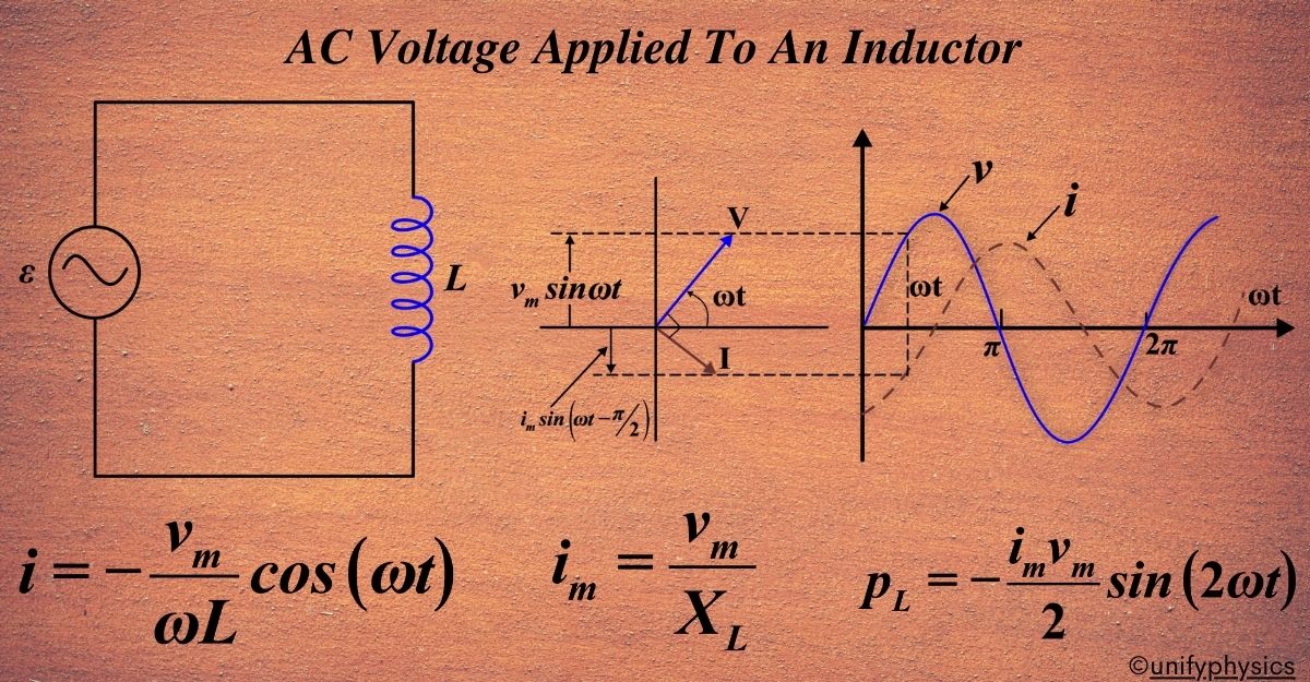
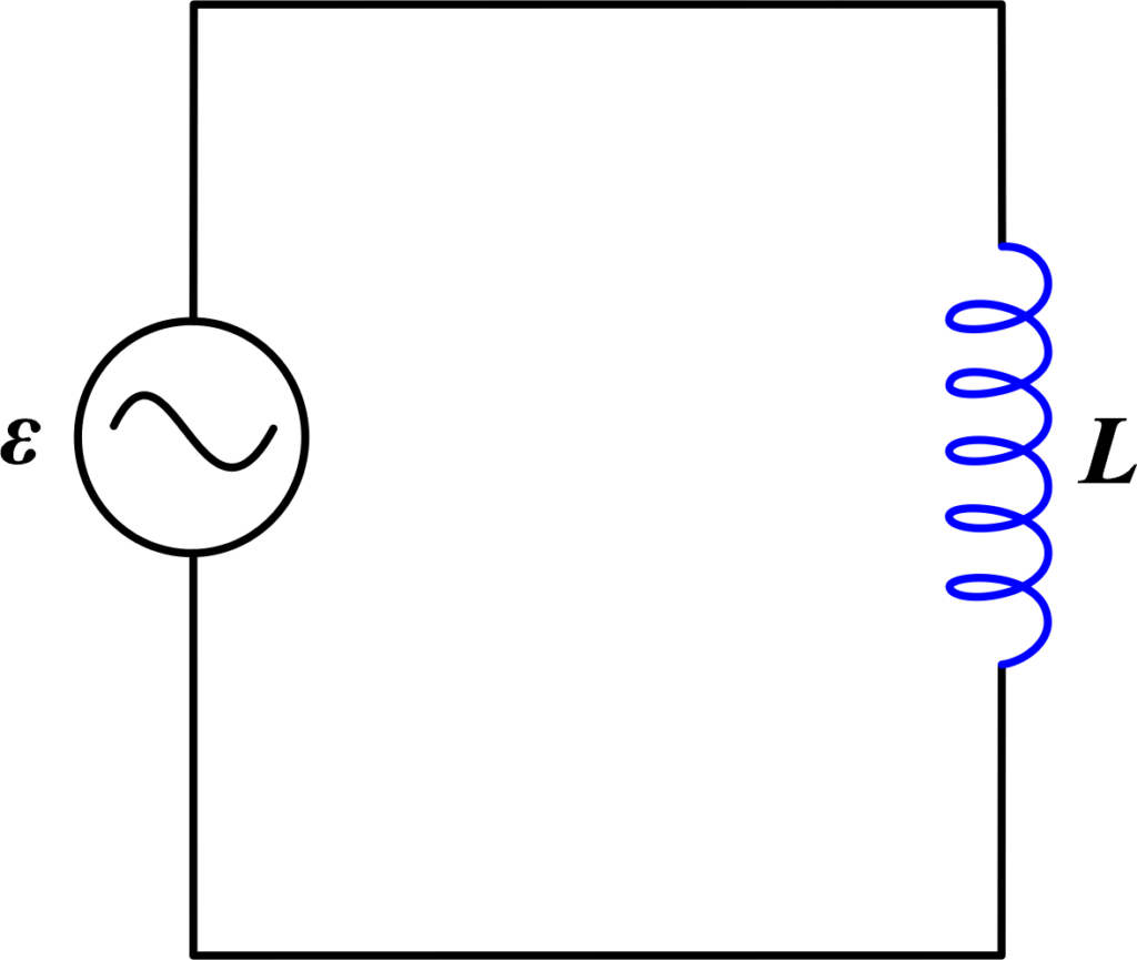
We’re diving into how electric circuits work when we connect an AC voltage to an inductor. To understand this, let’s look at a circuit. In the circuit, we have an inductor and an AC voltage source, which we show with this symbol ~. This AC voltage source makes the voltage across the inductor change in a wavy pattern, like a sine wave. We can express this changing voltage with an equation.
The AC voltage, v, can be given as:
\(\displaystyle v = v_m \sin(\omega t)\)
- vm is the amplitude of the oscillating potential,
- ω is the angular frequency.
Using Kirchhoff’s loop rule, which states that the sum of the potential differences (voltages) around any closed loop or mesh in a network is always equal to zero, we can write:
\(\displaystyle v – L \frac{di}{dt} = 0\)
Here, L is the self-inductance of the inductor, and \(\displaystyle\frac{di}{dt}\) is the rate of change of current. From this, we get the equation for the change in current as a function of time:
\(\displaystyle\frac{di}{dt} = \frac{v}{L} = \frac{v_m}{L} \sin(\omega t)\)
This equation tells us how the current changes with time, but it doesn’t give us the current itself. Its amplitude is given by (vm/L). To find the current, we need to integrate this equation with respect to time.
\(\displaystyle \int{{di=\int{{\frac{{{{v}_{m}}}}{L}\sin \left( {\omega t} \right)}}}}\)
\(\displaystyle i=-\frac{{{{v}_{m}}}}{{\omega L}}\cos \left( {\omega t} \right)\)
This is because the integral of \(\displaystyle\sin(\omega t)\) with respect to (t) is \(\displaystyle -\frac{1}{\omega} \cos(\omega t)\). The integral of the sine function is negative cosine, so we get:
\(\displaystyle i = -\frac{v_m}{\omega L} \cos(\omega t) + C\)
So, this is the equation for the current through an inductor when an AC voltage is applied.
\(\displaystyle\boldsymbol { i = -\frac{v_m}{\omega L} \cos(\omega t)}\)
Here, C is the integration constant, which represents the initial current through the inductor at t = 0. The “integration constant” is a part of a mathematical equation that stays the same no matter what. In this case, it’s related to the current in the circuit. Since the source of the electricity we’re using swings back and forth equally around zero (like an AC voltage), the current does the same thing. That means there’s no steady, unchanging part of the current. So, in this situation, the integration constant ends up being zero.
Also Read: AC Voltage Applied To A Resistor
\(\displaystyle -\cos \left( {\omega t} \right)=\sin \left( {\omega t-\frac{\pi }{2}} \right)\)
\(\displaystyle i={{i}_{m}}\sin \left( {\omega t-\frac{\pi }{2}} \right)\)
Where \(\displaystyle i_m = \frac{v_m}{\omega L} \) is the amplitude of the current. The quantity ωL is analogous to the resistance and is called inductive reactance, denoted by XL: XL = ω L The amplitude of the current is, then
\(\displaystyle\boldsymbol{ i_m = \frac{v_m}{X_L} }\)
Inductive reactance is measured in ohms, just like resistance. It’s a bit like resistance in a circuit with only inductors. Just as resistance slows down the flow of electricity in a regular circuit, inductive reactance slows down the flow of current in a circuit with just inductors.
The amount of inductive reactance depends on how big the inductor is and how fast the current is changing. If the inductor is bigger or if the current is changing more quickly, the inductive reactance will be greater too.
The current is a sinusoidal function, just like the voltage, but it is shifted by 90 degrees (or \(\displaystyle\pi/2) radians\), which is a characteristic of inductors in AC circuits. This phase shift is due to the inductor’s resistance to changes in current.
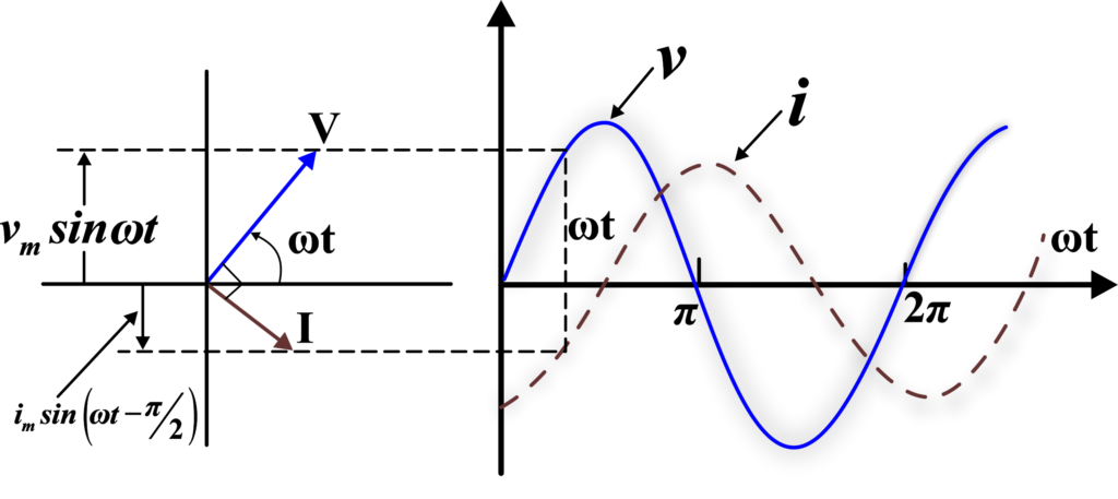
A comparison of Eqs. \(\displaystyle v = v_m \sin(\omega t)\) and \(\displaystyle i={{i}_{m}}\sin \left( {\omega t-\frac{\pi }{2}} \right)\) for the source voltage and the current in an inductor shows that the current lags the voltage by π/2 or one-quarter (1/4) cycle. The figure shows the voltage and the current phasors in the present case at instant t1. The current phasor I is π/2 behind the voltage phasor V.
We notice that the current peaks occur after the voltage peaks by one-fourth of the time it takes for a full cycle to complete. This time delay is equivalent to one-fourth of the period of the wave \(\displaystyle \left[ {\frac{T}{4}=\frac{{{\pi }/{2}\;}}{\omega }} \right]\).
Power Consumption
Firstly, power in electrical terms is the rate at which energy is used or transferred. It’s usually measured in watts (W). In a DC circuit, calculating power is straightforward: it’s the product of voltage (V) and current (I). But in an AC circuit, things get a bit more complex due to the changing nature of the voltage and current.
An inductor in an AC circuit behaves differently than in a DC circuit. When AC voltage is applied, the inductor resists changes in current flow through self-inductance. This resistance to change is due to the inductor’s ability to store energy in its magnetic field.
In an AC circuit, the voltage across an inductor leads the current by 90 degrees. This means when the voltage reaches its peak, the current is at zero, and vice versa. Because of this phase difference, the inductor does not consume power in the traditional sense.
In an ideal inductor (one without any resistance), the power consumed is zero. This is because the energy is not lost but rather stored temporarily in the magnetic field and then returned to the circuit. The formula for instantaneous power in an inductor is:
\(\displaystyle P(t) = V(t) \times I(t) \)
Since the voltage and current are out of phase by 90 degrees, their product averages to zero over a complete cycle, meaning no net power is consumed.
In the real world, inductors are not perfect and have some resistance. This resistance causes some power loss in the form of heat, but it’s typically very small compared to other components like resistors.
Imagine a playground seesaw with two children of equal weight sitting on opposite ends. They go up and down, but the seesaw itself doesn’t move from its central position. Similarly, energy in an inductor goes back and forth between the magnetic field and the circuit, but no energy is lost as power in the ideal case.
Instantaneous Power
Now, let’s see if this delayed current also consumes power, just like it does in a resistor. Let’s investigate further. The instantaneous power p supplied to any electrical device is given by the product of the instantaneous voltage v and the instantaneous current i. So, we have:
\(\displaystyle p = vi\)
Now, we know that in an inductor, the voltage and current are given by:
\(\displaystyle v = v_m \sin(\omega t)\)
\(\displaystyle i = i_m \sin(\omega t – \frac{\pi}{2})\)
Substituting these into the power equation gives us:
\(\displaystyle p = v_m \sin(\omega t) \cdot i_m \sin(\omega t – \frac{\pi}{2})\)
We can simplify this using the trigonometric identity for the product of sines:
\(\displaystyle\sin(A) \sin(B) = \frac{1}{2}[\cos(A – B) – \cos(A + B)]\)
So, we get:
\(\displaystyle p = \frac{1}{2} v_m i_m [\cos(\frac{\pi}{2}) – \cos(2\omega t – \frac{\pi}{2})]\)
Since \(\displaystyle \cos(\pi/2) = 0\), this simplifies to:
\(\displaystyle p = -\frac{1}{2} v_m i_m \cos(2\omega t – \frac{\pi}{2})\)
Now, we know from trigonometry that \(\displaystyle\cos(\theta – \frac{\pi}{2})\) is equivalent to \(\displaystyle\sin(\theta)\). This is because the cosine function leads the sine function by a phase of \(\displaystyle\frac{\pi}{2}\) radians (or 90 degrees).
So, we can rewrite the equation as:
\(\displaystyle \boldsymbol{ p_L = -\frac{i_m v_m}{2} \sin(2\omega t)}\)
The negative sign indicates that the power is being returned to the circuit half the time, which is a characteristic of reactive components like inductors and capacitors.
So, the average power over a complete cycle is
\(\displaystyle p_{L} = \left\langle -\frac{i_m v_m}{2} \sin(2\omega t) \right\rangle \)
\(\displaystyle p_{L} = -\frac{i_m v_m}{2} \left\langle \sin(2\omega t) \right\rangle = 0 \)
Since the average of sin (2ωt) over a complete cycle is zero. Thus, the average power supplied to an inductor over one complete cycle is zero.
Examples
Example 1: An AC voltage source with a frequency of 50 Hz is applied to an inductor with an inductance of 0.02 H Calculate the reactance of the inductor.
Solution: The reactance XL of an inductor in an AC circuit is given by the formula:
\(\displaystyle X_L = 2\pi f L \)
where f is the frequency and ( L ) is the inductance. Given that f = 50 Hz and L = 0.02 H we can calculate the reactance:
\(\displaystyle X_L = 2\pi \times 50 \times 0.02 \)
\(\displaystyle X_L = 2\pi \, \Omega \)
Therefore, the reactance of the inductor is \(\displaystyle 2\pi \, \Omega \).
Example 2: An AC voltage source with a frequency of 100 Hz and an effective voltage of 10 V is applied to an inductor. If the current lags the voltage by (π/4) radians, calculate the inductance of the inductor.
Solution: In an AC circuit, the relationship between voltage V, current I, frequency f, and inductance L, for an inductor is given by:
\(\displaystyle V = IXL \)
Given that the current lags the voltage by (π/4) radians, we know that the phase angle (θ = -π/4). Therefore, we have:
\(\displaystyle X_L = \frac{V}{I} = \frac{V}{V/X_L} = X_L^2 = \frac{V^2}{V} = V \)
\(\displaystyle X_L = 10 \, \Omega \)
We use the formula for reactance:
\(\displaystyle X_L = 2πfL \)
Substituting the given values, we can solve for L:
\(\displaystyle 10 = 2π \times 100 \times L \)
\(\displaystyle L = \frac{10}{200π} \)
\(\displaystyle L = \frac{1}{20π} \, \text{H} \)
Therefore, the inductance of the inductor is \(\displaystyle\frac{1}{20π} \, \text{H} \).
Example 3: An AC voltage source with an effective voltage of 20 V and a frequency of 60 Hz is applied to an inductor. If the current through the inductor is 1 A, determine the inductance of the inductor.
Solution: Given parameters:
- Effective Voltage Veff = 20 V
- Frequency f = 60 Hz
- Current I = 1 A
We know that the reactance XL of an inductor is given by:
\(\displaystyle X_L = \frac{V_{\text{eff}}}{I} \)
The formula for the reactance of an inductor is:
\(\displaystyle X_L = 2πfL \)
Equating both expressions for XL we get:
\(\displaystyle \frac{V_{\text{eff}}}{I} = 2πfL \)
\(\displaystyle L = \frac{V_{\text{eff}}}{2πfI} \)
Substituting the given values:
\(\displaystyle L = \frac{20}{2π \times 60 \times 1} \)
\(\displaystyle L = \frac{20}{120π} \)
\(\displaystyle L = \frac{1}{6π} \, \text{H} \)
Therefore, the inductance of the inductor is \(\displaystyle \frac{1}{6π} \, \text{H} \).
Example 4: An AC voltage source with a frequency of 50 Hz is applied to an inductor. If the reactance of the inductor is 10 Ω, calculate the inductance of the inductor.
Solution: Given parameters:
- Frequency f = 50 Hz
- Reactance XL = 10 Ω
We know that the reactance XL of an inductor is given by:
\(\displaystyle X_L = 2πfL \)
Solving for inductance L:
\(\displaystyle L = \frac{X_L}{2πf} = \frac{10}{2π \times 50} = \frac{10}{100π} \)
\(\displaystyle L = \frac{1}{10π} \, \text{H}\)
Therefore, the inductance of the inductor is \(\displaystyle\frac{1}{10π} \, \text{H} \).
Example 5: An AC voltage source with an effective voltage of 30 V and a frequency of 100 Hz is applied to an inductor. If the inductance of the inductor is 0.02 H, calculate the current through the inductor.
Solution: Given parameters:
- Effective Voltage Veff = 30 V
- Frequency f = 100 Hz
- Inductance L = 0.02 H
We know that the reactance XL of an inductor is given by:
\(\displaystyle X_L = 2πfL \)
The formula for current (I) through the inductor is:
\(\displaystyle I = \frac{V_{\text{eff}}}{X_L} \)
Substituting the given values:
\(\displaystyle X_L = 2π \times 100 \times 0.02 = 4π \, \text{Ω} \)
\(\displaystyle I = \frac{30}{4π} \)
Therefore, the current through the inductor is
\(\displaystyle\frac{30}{4π} \) amperes.
FAQs
What happens when AC voltage is applied to an inductor?
When AC voltage is applied to an inductor, the inductor resists changes in current due to its property of inductance. This creates a phase difference where the current lags behind the voltage by 90 degrees.
How does an inductor react to a sinusoidal AC voltage?
An inductor generates an electromotive force (emf) that opposes the change in current through it. This causes the current in the inductor to change more slowly than the voltage, resulting in the current lagging the voltage by 90 degrees.
Why does the current lag the voltage in an AC circuit with an inductor?
The current lags the voltage in an AC circuit with an inductor because the inductor resists changes in current due to its inductance. The induced emf opposes the current change, causing the current to reach its maximum value after the voltage has reached its maximum value.
What is the phase relationship between voltage and current in an inductor when AC voltage is applied?
The phase relationship is such that the current lags behind the voltage by 90 degrees. This means that when the voltage reaches its peak, the current is at zero, and when the current reaches its peak, the voltage is at zero.
How does the inductive reactance affect the AC circuit?
Inductive reactance determines the opposition that the inductor provides to the AC current. It is proportional to the frequency of the AC signal and the inductance of the inductor. Higher inductive reactance results in a greater phase lag between voltage and current.
Can you explain the concept of inductive reactance in simple terms?
Inductive reactance is the resistance that an inductor provides to the flow of AC current. It increases with the frequency of the AC signal and the inductance value, causing the current to lag behind the voltage.
What practical applications utilize the behavior of inductors in AC circuits?
Inductors in AC circuits are used in various applications such as transformers, filters, inductive sensors, and energy storage devices in power supplies. They help in managing current flow, filtering signals, and storing energy in magnetic fields.