The concept of LC oscillations has its roots in the exploration of electrical phenomena in the late 19th and early 20th centuries. During this period, scientists were discovering the fundamental principles of electromagnetism that would eventually lead to the development of modern electronics.
One of the key figures in the study of LC oscillations was the American engineer Edwin H. Colpitts, who is credited with inventing the LC oscillator circuit in 1918. This circuit, which is a type of electronic oscillator, uses an inductor (L) and a capacitor (C) to create electrical oscillations at a desired frequency.
The LC circuit, also known as a resonant or tuned circuit, is an idealized model that assumes no energy loss due to resistance. In reality, any practical implementation of an LC circuit will include some resistance, but studying the ideal form helps us understand the underlying principles.
LC circuits became fundamental components in many electronic devices, particularly in radio equipment. They are used in oscillators, filters, tuners, and frequency mixers. The ability of LC circuits to select specific frequencies made them indispensable in the era of radio communication.
Understanding LC Oscillations
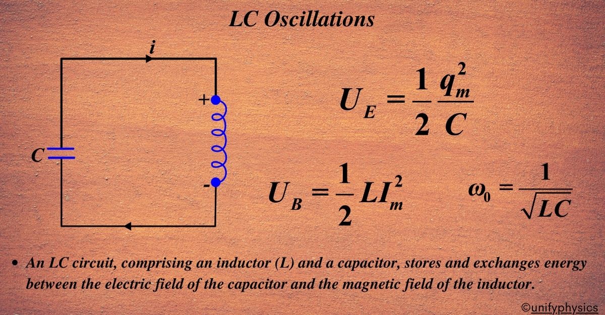
LC oscillations occur in a circuit where a capacitor and an inductor are connected. This type of circuit is known as an LC circuit, and it’s a fundamental concept in the study of physics, especially when dealing with alternating current (AC) circuits.
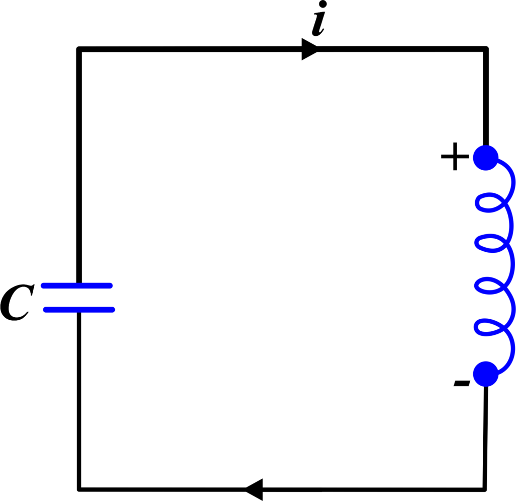
An LC circuit consists of two main components:
- L (Inductor): A coil that stores energy in its magnetic field.
- C (Capacitor): A device that stores energy in its electric field.
When these two components are connected, they can exchange energy, creating oscillations.
How LC Oscillations Occur
Imagine you have a charged capacitor. When connected to an inductor, the capacitor will start to discharge, transferring its energy to the inductor and creating a magnetic field around it. As the capacitor’s charge decreases, the current in the circuit increases until the capacitor is fully discharged.
At this point, the inductor will start to oppose the change in current (thanks to Lenz’s Law), and it will ‘push back’, causing the capacitor to charge again, but in the opposite polarity. This back-and-forth exchange of energy between the capacitor and inductor creates an oscillation.
The Equations
The energy in the capacitor (UE) is given by:
\(\displaystyle U_E = \frac{1}{2} \frac{q_m^2}{C} \)
Where (qm) is the maximum charge on the capacitor. The energy in the inductor (UB) when the current is at its maximum (Im) is:
\(\displaystyle U_B = \frac{1}{2} L I_m^2 \)
The charge (q) and the current (I) in the circuit oscillate sinusoidally with time, and the frequency of oscillation \(\displaystyle\omega_0 \) is determined by the inductance (L) and the capacitance (C):
\(\displaystyle \omega_0 = \frac{1}{\sqrt{LC}} \)
This frequency is known as the natural frequency of the LC circuit.
Real-World Considerations
In a perfect world, these oscillations would continue indefinitely. However, in real circuits, there’s always some resistance which causes energy to be lost as heat. Additionally, some energy may be radiated away as electromagnetic waves. These factors lead to damping of the oscillations, and over time, they will diminish unless external energy is supplied to the circuit.
Understanding LC oscillations is crucial for designing various electronic devices, especially those involving radio frequency (RF) circuits, filters, and tuners. It’s a beautiful demonstration of energy transformation and conservation in physics.
By grasping the concept of LC oscillations, students can appreciate the interplay between electric and magnetic fields and how they govern the behavior of AC circuits. It’s a stepping stone towards more advanced topics in electromagnetism and electronics.
Let’s derive these two important equations related to the energy stored in a capacitor and an inductor, which are key concepts in the physics of circuits.
Also Read: AC Voltage Applied to a Series LCR Circuit
Derivation of Energy Stored in a Capacitor
The energy stored in a capacitor (denoted as ( UE ) can be derived from the work done to move charge from one plate to another against the electric field.
When a small amount of charge (dq) is transferred from one plate to another, the work done (dW) is equal to the potential difference (V) times (dq):
\(\displaystyle dW = V \cdot dq \)
The potential difference (V) across the capacitor is related to the charge (q) by the equation \(\displaystyle V = \frac{q}{C} \), where (C) is the capacitance. Substituting this into the expression for work done, we get:
\(\displaystyle dW = \frac{q}{C} \cdot dq \)
To find the total work done (W) when a charge (qm) is moved, we integrate (dW) from 0 to (qm):
\(\displaystyle W = \int_{0}^{q_m} \frac{q}{C} \cdot dq = \frac{1}{2} \frac{q_m^2}{C} \)
This work done is stored as electrical potential energy in the capacitor, hence:
\(\displaystyle\boldsymbol{ U_E = \frac{1}{2} \frac{q_m^2}{C} }\)
This equation represents the maximum potential energy stored in the capacitor when it is fully charged, and it corresponds to the point in the oscillation where all the energy is in the electric field of the capacitor and none in the magnetic field of the inductor.
Derivation of Energy Stored in an Inductor
The energy stored in an inductor (denoted as (UB) is derived from the work required to establish the current through the inductor against the self-induced emf.
When a current (I) is established in an inductor (L), the power (P) required at any instant is given by:
\(\displaystyle P = L \frac{dI}{dt} \cdot I \)
The work done (dW) in a small time interval (dt) is the power multiplied by (dt):
\(\displaystyle dW = P \cdot dt = L I \frac{dI}{dt} \cdot dt \)
To find the total energy (UB) stored when the current increases from 0 to (Im), we integrate (dW) from 0 to ( Im ):
\(\displaystyle U_B = \int_{0}^{I_m} L I \cdot dI = \frac{1}{2} L I_m^2 \)
This energy is stored as magnetic potential energy in the magnetic field around the inductor, hence:
\(\displaystyle\boldsymbol{ U_B = \frac{1}{2} L I_m^2 }\)
These derivations show how energy is stored in a capacitor’s electric field and an inductor’s magnetic field, which are fundamental concepts for understanding the behavior of AC circuits and the principles of energy conservation in physics.
The Mechanical-Electrical Analogy
In a mechanical system, we deal with objects in motion, forces, and energy. These concepts have direct counterparts in electrical systems, which deal with charges, potentials, and electromagnetic energy. Understanding these analogies can simplify complex ideas and provide a clearer picture of how different physical systems operate under similar principles.
- Mass and Inductance (L): Just as mass represents the inertia of an object in motion, inductance represents the ‘electrical inertia’ of a circuit. It’s the property that resists changes in current flow, analogous to how mass resists changes in velocity.
- Force Constant and Reciprocal Capacitance (1/C): The force constant in a spring determines how much it resists compression or extension, similar to how the reciprocal of capacitance indicates how much a capacitor resists changes in voltage.
- Displacement and Charge (q): Displacement in mechanics refers to the change in position, while in electricity, charge represents the quantity of electricity. Both are fundamental to their respective fields.
- Velocity and Current (i = dq/dt): Velocity is the rate of change of displacement, and current is the rate of change of charge. They are the ‘flow’ rates in their respective systems.
- Energy Equations: The mechanical energy equation
\(\displaystyle\boldsymbol{ E = \frac{1}{2} kx^2 + \frac{1}{2} mv^2 }\)
has its electrical analog in
\(\displaystyle\boldsymbol{ U = \frac{1}{2} \frac{q^2}{C} + \frac{1}{2} Li^2 }. \)
- These equations show the conservation of energy in both systems, where energy oscillates between kinetic and potential forms in mechanics and between electric and magnetic fields in electricity.
FAQs
What are LC oscillations?
- LC oscillations refer to the periodic oscillations that occur in an LC circuit consisting of an inductor (L) and a capacitor (C) connected in series or parallel. These oscillations occur due to the exchange of energy between the magnetic field of the inductor and the electric field of the capacitor.
How does the charge on the capacitor vary during LC oscillations?
- The charge on the capacitor (Q) during LC oscillations follows a sinusoidal pattern. It reaches its maximum value when the energy stored in the capacitor is maximum and decreases to zero as the capacitor discharges. The charge then becomes negative as the capacitor charges in the opposite direction, leading to oscillatory behavior.
What is the phase relationship between voltage and current in an LC circuit during oscillations?
- In an LC circuit during oscillations, the voltage across the capacitor leads the current through the inductor by 90∘. This phase relationship results from the behavior of the capacitor and inductor in storing and releasing energy at different points in the oscillation cycle.
What is the natural frequency of an LC circuit?
- The natural frequency of an LC circuit, often denoted as (ω0 ), is the frequency at which the system naturally oscillates without external influence. It is determined by the formula:
$$ \omega_0 = \frac{1}{\sqrt{LC}} $$
Why is the LC circuit also called a tank circuit?
- The LC circuit is sometimes referred to as a tank circuit because it can ‘store’ energy, much like a water tank stores water. In this analogy, the capacitor is like the tank’s volume, and the inductor is like the pipe’s width, determining how quickly water can flow in and out.
What factors affect the damping of LC oscillations?
- The damping of LC oscillations is affected by factors such as resistance (R) in the circuit, which leads to energy dissipation and reduces the amplitude of oscillations over time. Higher resistance leads to faster damping, while lower resistance allows for more sustained oscillations.
How does the amplitude of LC oscillations change with different initial conditions?
- The amplitude of LC oscillations depends on the initial conditions of the circuit, such as the initial charge on the capacitor or the initial current through the inductor. A higher initial charge or current leads to larger oscillation amplitudes, while a lower initial charge or current results in smaller oscillation amplitudes.