The story of Motional EMF begins with the pioneering work of Alessandro Volta in the early 19th century. In 1801, Volta introduced the term “force motrice électrique” to describe the active agent of a battery, which he had invented around 1798. This term translates to “electromotive force” in English and marks the first use of the concept of EMF.
Fast forward to the 1830s, when Michael Faraday and Joseph Henry independently discovered electromagnetic induction. They observed that moving a conductor through a magnetic field could induce an electric current in the conductor. This phenomenon is the basis of motional EMF.
Faraday’s experiments showed that the induced EMF in a circuit is directly related to the rate of change of the magnetic flux through the circuit. This discovery is fundamental to understanding how generators and transformers work, which are essential components of our modern electrical infrastructure.
The development of these concepts led to the formulation of Faraday’s Law of Induction, which mathematically describes how a change in magnetic flux can induce an EMF in a conductor. This law, along with Lenz’s Law, which describes the direction of the induced current, forms the cornerstone of our understanding of motional EMF.
EMF
Electromotive Force (EMF) is not a force but a potential difference measured in volts. It’s the energy provided per charge that passes through a power source, like a battery or generator.
Imagine you’re at a water park. There’s a slide with water flowing down it. The water at the top has potential energy due to its height. When it starts sliding down, this potential energy turns into kinetic energy, making the water flow. Now, replace the water with electric charges, and the height with a power source like a battery or generator. That’s where EMF comes into play.
EMF is like the push that gets the electric charges moving. It’s not a physical force like gravity or magnetism, but it’s a measure of energy given to each charge to move through a circuit. It’s the initial boost that starts the flow of electricity.
Despite its name, EMF is not a force. It’s a potential difference, which means it’s the energy provided per charge by a power source. EMF is measured in volts (V), which is the standard unit for potential difference.
The basic formula for EMF is
\(\displaystyle \varepsilon = V + Ir \)
where (\(\displaystyle\varepsilon \)) is the EMF, (V) is the voltage across the external circuit, (I) is the current, and (r) is the internal resistance of the power source.
The dimension of EMF is [M L2 T-3 A-1], which aligns with its nature as an energy per charge.
When you connect a battery to a circuit, the EMF is what drives the current around the circuit. It’s like the battery is saying to the charges, “Come on, let’s go for a ride!” and gives them the energy to start moving.
It’s important to distinguish between EMF and voltage:
- EMF is the energy supplied by the source when no current is flowing.
- Voltage is the energy used by the charges as they move through the circuit.
Think of EMF as the amount of money you have to spend on a shopping trip (the energy available), and voltage as the actual amount you spend in each shop (the energy used).
What is Motional EMF?
Motional EMF is generated when a conductor moves through a magnetic field, causing a separation of charges within the conductor and thus creating a voltage.
Imagine you’re riding a bicycle with a dynamo light. As you pedal faster, the light gets brighter. This happens because the motion of the bicycle wheel in the magnetic field of the dynamo generates an electric current, lighting up the bulb. This is a practical example of Motional Electromotive Force (EMF).
Motional EMF is the voltage generated when a conductor, like a wire or a metal rod, moves through a magnetic field. The movement creates a flow of electric charges, which we see as an electric current.
When a conductor moves through a magnetic field, the magnetic field exerts a force on the free electrons in the conductor. This force pushes the electrons, which creates a flow of electric current.
The strength of the motional EMF depends on how the conductor interacts with the magnetic field. If it moves parallel to the magnetic field lines, no EMF is induced. But if it cuts across the field lines, that’s when the magic happens, and EMF is generated.
The amount of EMF produced can be calculated using the formula:
\(\displaystyle \text{EMF} = B \cdot L \cdot V \cdot \sin(\theta) \)
- (B) is the magnetic field strength,
- (L) is the length of the conductor within the magnetic field,
- (V) is the velocity of the conductor,
- (θ) is the angle between the conductor’s direction of motion and the magnetic field lines.
Back to our bicycle dynamo: as you pedal, the wheel (conductor) moves through the earth’s magnetic field. The faster you pedal (higher velocity), the more the dynamo cuts through the magnetic field lines, and the more EMF is generated, making the light brighter.
A simple experiment to demonstrate motional EMF involves moving a magnet through a coil of wire connected to a galvanometer. As the magnet moves in and out of the coil, the galvanometer needle swings, indicating the presence of an electric current due to the motional EMF.
Experiments Demonstrating Motional EMF
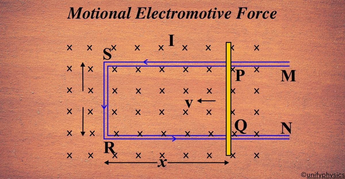
A rectangular loop of wire, labeled PQRS, is placed in a uniform magnetic field, which is represented by the blue ‘X’ symbols. These symbols indicate that the magnetic field is directed into the plane of the paper/screen. The loop is being pulled to the right with a velocity \(\displaystyle\vec{V}\). As the loop moves, sides PS and QR of the loop cut through the magnetic field lines.
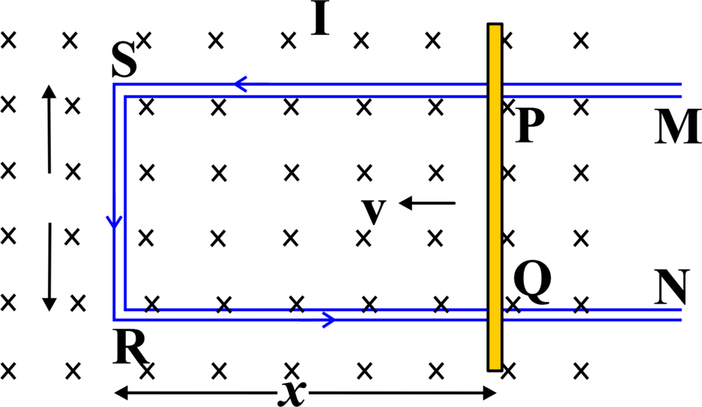
Because of this, a current I is created in the loop.
Due to the movement of the loop through the magnetic field, an EMF is induced in the sides PS and QR of the loop. According to Faraday’s law of electromagnetic induction, the induced EMF \(\displaystyle \varepsilon\) in a segment of the wire moving through a magnetic field is given by:
\(\displaystyle\varepsilon = B \cdot l \cdot v \cdot \sin(\theta)\)
The direction of the induced current (I) in the loop can be determined using Fleming’s Right-Hand Rule. Point your thumb in the direction of the velocity \(\displaystyle\vec{V}\), your index finger in the direction of the magnetic field, and your middle finger point in the direction of the induced current. A galvanometer or meter (M) is connected between points P and Q, showing deflection due to the induced current (I). The deflection indicates that an EMF has been generated, and if the circuit is complete, a current flows through it. This experiment demonstrates motional EMF, showing that when a conductor moves through a magnetic field, an EMF gets induced across it, which can drive a current if the circuit is closed.
Derivation For Motional EMF
Imagine you have a metal rod and you’re moving it through a magnetic field. As you move the rod, an electric current starts flowing through it. But how does this happen?
Suppose, you have a conductor (like a metal rod) of length (L). It’s moving at a velocity (v) through a uniform magnetic field (B). The conductor is moving perpendicular to the magnetic field.
As the conductor moves, the free electrons in the metal experience a magnetic force. This force is given by the Lorentz force law, which states that a charged particle moving in a magnetic field will experience a force.
The formula for the magnetic force (F) on a charge (q) is:
\(\displaystyle F = qvB \sin(\theta) \)
where (θ) is the angle between the velocity and the magnetic field. Since the rod is moving perpendicular to the field, (\(\displaystyle\sin(\theta) = 1 \)).
Now, EMF (\(\displaystyle\varepsilon \)) is defined as the work done per unit charge. So, we can write:
\(\displaystyle \varepsilon = \frac{Work}{q} \)
The work done by the magnetic force as the conductor moves through the field is:
\(\displaystyle Work = F \cdot L \)
Substituting the expression for (F) from above, we get:
\(\displaystyle \varepsilon = \frac{qvBL}{q} \)
Simplifying, we find the formula for motional EMF:
\(\displaystyle \varepsilon = B \cdot L \cdot v \)
This formula tells us that the EMF induced in the conductor depends on the strength of the magnetic field (B), the length of the conductor (L), and the velocity (v) with which it moves through the field.
The derivation shows that when you move a conductor through a magnetic field, it’s like giving the free electrons in the conductor a little push. This push, caused by the magnetic force, creates a flow of electrons, which we see as an electric current. The faster you move the rod or the stronger the magnetic field, the greater the push and the higher the EMF. It’s like running faster through a crowd—the faster you go, the more people you’ll push along with you!
Factors that Affect the Induced Electromotive Force
Think of induced EMF as the result of a dance between a conductor (like a wire) and a magnetic field. The way they move together and the environment they’re in can change the energy of their dance, which in this case, is the EMF. Here are the main factors:
- Rate of Relative Motion: The faster the conductor moves through the magnetic field or the faster the magnetic field changes around the conductor, the greater the induced EMF. It’s like dancing faster to the music—the quicker you move, the more energy you have.
- Strength of the Magnetic Field: A stronger magnetic field means a stronger push on the electrons in the conductor, leading to a higher induced EMF. Imagine dancing with a stronger partner who leads firmly—you’re likely to move with more energy.
- Number of Turns in the Coil: If the conductor is part of a coil, more turns will mean more cutting of magnetic field lines and a higher induced EMF. It’s like having more dancers in a line; the longer the line, the more impressive the wave.
- Size of the Coil: Larger coils can cut through more magnetic field lines at once, increasing the induced EMF. Think of it as a larger dance floor allowing for bigger, more energetic dance moves.
- Orientation of the Conductor: The angle at which the conductor moves through the magnetic field affects the induced EMF. Moving perpendicular to the field lines induces the most EMF, similar to how certain dance moves work best when done in a specific direction.
To help visualize these factors, imagine you’re on a swing (the conductor) in a playground (the magnetic field). The higher you swing (strength of the field) and the faster you go (rate of motion), the more wind you’ll feel (induced EMF). If you have friends swinging alongside you (turns in the coil) and you all swing in sync (orientation), the collective breeze (EMF) is even stronger.
Lenz’s Law And Motional EMF
Lenz’s Law states that the direction of the induced EMF and the resulting current will be such that it opposes the change in magnetic flux that produced it. This is a manifestation of the conservation of energy.
Lenz’s law is integral to understanding motional EMF. It ensures that the induced EMF creates a current whose magnetic field opposes the original change in flux. This is a manifestation of the conservation of energy, as it prevents the system from creating energy out of nothing.
The negative sign in the motional EMF formula represents Lenz’s Law. It indicates that the induced EMF will always work to oppose the change in magnetic flux. For example, if a conductor moves through a magnetic field, the induced EMF will generate a current that creates a magnetic field opposing the motion of the conductor. This opposition is a natural consequence of energy conservation; it prevents the system from spontaneously increasing its energy without an external work input.
Imagine you have a magnet and a coil of wire. If you move the magnet towards the coil, you’ll notice that electricity starts flowing in the coil. This is because of the motional EMF we talked about earlier. But which way does the current flow? That’s where Lenz’s Law comes in.
Lenz’s Law is like the universe’s way of saying, “I don’t like change.” It tells us that any induced current will flow in a direction that opposes the change that caused it. So, if you push a magnet towards a coil, the coil will create a current that produces a magnetic field to push back against the magnet.
When you move a conductor through a magnetic field, Lenz’s Law ensures that the induced EMF creates a current that opposes the motion. This means if you’re pushing the conductor into a region with a stronger magnetic field, the induced current will try to push it back out.
In a generator, when the coil spins in the magnetic field, Lenz’s Law is at play, ensuring that the current produced fights the spin, which is why generators need a push to keep going. It’s like pedaling a bike uphill; you have to keep pedaling against gravity (the induced current) to maintain your speed (the motion).
Understanding the relationship between Lenz’s Law and motional EMF is essential for explaining the operation of electrical generators, where mechanical motion is converted into electrical energy, and electric motors, where electrical energy is converted into mechanical motion. In both cases, Lenz’s Law ensures that energy is conserved and that the system behaves predictably according to the fundamental laws of physics.
Also Read: Lenz’s Law
Applications of Motional EMF
Motional EMF isn’t just a cool concept you learn in physics class; it’s actually used in a lot of things around us. Here are some of the ways it’s applied:
- Electric Generators: These are like the powerhouses of our world. They convert mechanical energy (like the spinning of a turbine) into electrical energy we use to power everything from lights to computers. The motion of coils within a magnetic field in generators is what creates the EMF.
- Induction Cooktops: Ever wonder how an induction stove heats a pot without a flame? It’s all thanks to motional EMF. A changing magnetic field underneath the cooktop surface induces currents in the pot, which heats it up without any need for a traditional heat source.
- Speed Sensors: These are used in cars and other vehicles to figure out how fast they’re going. The sensor has a coil that, when moved through a magnetic field, induces an EMF. The strength of this EMF can tell us the speed of the vehicle.
- Magnetic Levitation Trains (Maglev): These super-fast trains float above the tracks thanks to magnetic fields. The principle of motional EMF is used here to create the forces needed to lift and propel the train forward.
- Airplanes: When airplanes fly through the Earth’s magnetic field, there’s an induced EMF generated between the wingtips. This can be measured and has practical implications for the aircraft’s systems.
Solved Examples
Problem 1: A wire of length 0.5 meters moves at a velocity of 2 m/s perpendicular to a magnetic field of strength 0.5 T. Calculate the motional EMF induced in the wire.
Solution: Given: Length of wire (l) = 0.5 m, Velocity (v) = 2 m/s, Magnetic field strength (B) = 0.5 T.
Using the formula for motional EMF:
\(\displaystyle \varepsilon =Blv\)
We plug in the values:
\(\displaystyle \varepsilon =0.5\times 0.5\times 2=0.5V\)
Therefore, the motional EMF induced in the wire is 0.5 volts.
Problem 2: A wire of length 0.5 meters moves perpendicular to a magnetic field of 0.2 teslas at a speed of 5 m/s. Calculate the motional EMF induced in the wire.
Solution: Using the formula for motional EMF, we have:
\(\displaystyle\varepsilon = -\frac{d\Phi}{dt} \)
\(\displaystyle\varepsilon = -B \cdot \frac{dA}{dt}\)
Given that the length of the wire (l) is 0.5 meters, and the velocity (v) is 5 m/s, the area (A) of the loop is given by:
\(\displaystyle A = l \times v \)
\(\displaystyle A = 0.5 \, \text{m} \times 5 \, \text{m/s} = 2.5 \, \text{m}^2 \)
Now, the rate of change of area (\(\displaystyle\frac{dA}{dt} \)) is simply the velocity (v) since the length of the wire is constant:
\(\displaystyle\frac{dA}{dt} = v = 5 \, \text{m/s}\)
Given that the magnetic field (B) is 0.2 teslas, we can calculate the motional EMF:
\(\displaystyle\varepsilon = -B \cdot \frac{dA}{dt}\)
\(\displaystyle\varepsilon = -0.2 \, \text{T} \times 5 \, \text{m/s} = -1.0 \, \text{V}\)
So, the motional EMF induced in the wire is 1.0 volts.
Problem 3: A rectangular loop of wire with dimensions (\(\displaystyle0.4 \, \text{m} \times 0.2 \, \text{m} \)) is pulled out of a uniform magnetic field of (0.6 T) at a constant velocity of (3 m/s). The loop is moving perpendicular to the magnetic field. Calculate the induced EMF and the direction of the induced current in the loop.
Solution: Using the formula for induced EMF in a moving conductor:
\(\displaystyle \mathcal{E} = B \cdot l \cdot v \)
Given:
- Length (l = 0.4 m)
- Velocity (v = 3 m/s)
- Magnetic field (B = 0.6 T)
Calculate the induced EMF:
\(\displaystyle \mathcal{E} = 0.6 \cdot 0.4 \cdot 3 \)
\(\displaystyle \mathcal{E} = 0.72 \, \text{V} \)
Using Lenz’s Law, the induced current will flow in a direction that opposes the change in magnetic flux. Since the loop is being pulled out of the magnetic field, the induced current will flow in such a way as to create a magnetic field that opposes this removal, resulting in a counterclockwise current if viewed from the side being pulled out.
The induced EMF is (0.72 V), and the induced current flows counterclockwise.
Problem 4: A circular coil with 50 turns and a radius of (0.1 m) is placed in a magnetic field that increases uniformly from (0.2 T) to (1.0 T) in (0.5 s). Calculate the induced EMF in the coil.
Solution: Using Faraday’s Law:
\(\displaystyle \mathcal{E} = -N \frac{d\Phi}{dt} \)
Given:
- Number of turns (N = 50)
- Radius (r = 0.1 m)
- Initial magnetic field (Bi = 0.2 T)
- Final magnetic field (Bf = 1.0 T)
- Time interval (∆t = 0.5 s)
Area of the coil:
\(\displaystyle A = \pi r^2 \)
\(\displaystyle A = \pi (0.1)^2 \)
\(\displaystyle A = 0.01\pi \, \text{m}^2 \)
Change in magnetic flux:
\(\displaystyle \Delta \Phi = A (B_f – B_i) \)
\(\displaystyle \Delta \Phi = 0.01\pi (1.0 – 0.2) \)
\(\displaystyle \Delta \Phi = 0.01\pi \cdot 0.8 \)
\(\displaystyle \Delta \Phi = 0.008\pi \, \text{Wb} \)
Average induced EMF:
\(\displaystyle \mathcal{E} = -N \frac{\Delta \Phi}{\Delta t} \)
\(\displaystyle \mathcal{E} = -50 \frac{0.008\pi}{0.5} \)
\(\displaystyle \mathcal{E} = -50 \cdot 0.016\pi \)
\(\displaystyle \mathcal{E} = -0.8\pi \)
\(\displaystyle \mathcal{E} \approx -2.51 \, \text{V} \)
The induced EMF in the coil is (-2.51 V).
Problem 5: A square loop of side (0.3 m) is rotating in a uniform magnetic field of (0.4 T). The plane of the loop is perpendicular to the magnetic field at (t = 0) and rotates with an angular velocity of (50 rad/s). Determine the maximum induced EMF in the loop.
Solution: Using Faraday’s Law for a rotating loop:
\(\displaystyle\mathcal{E} = -N \cdot A \cdot B \cdot \omega \cdot \sin(\omega t) \)
Given:
- Side of the square loop (l = 0.3 m)
- Magnetic field (B = 0.4 T)
- Angular velocity (ω = 50 rad/s)
Area of the loop:
\(\displaystyle A = l^2 \)
\(\displaystyle A = (0.3)^2 \)
\(\displaystyle A = 0.09 \, \text{m}^2 \)
Maximum induced EMF occurs when (\(\displaystyle \sin(\omega t) = 1 \)):
\(\displaystyle \mathcal{E}{\text{max}} = A \cdot B \cdot \omega \)
\(\displaystyle \mathcal{E}{\text{max}} = 0.09 \cdot 0.4 \cdot 50\)
\(\displaystyle \mathcal{E}_{\text{max}} = 1.8 \, \text{V} \)
The maximum induced EMF in the loop is (1.8 V).
Problem 6: A solenoid with 400 turns and a length of (0.4 m) has a cross-sectional area of (0.01 m2). If the current through the solenoid changes uniformly from (1 A) to (4 A) in (0.2 s), calculate the induced EMF in the solenoid.
Solution: Using Faraday’s Law:
\(\displaystyle \mathcal{E} = -N \frac{d\Phi}{dt} \)
Magnetic flux in a solenoid:
\(\displaystyle \Phi = B \cdot A \)
\(\displaystyle B = \mu_0 \frac{N}{l} I \)
Given:
- Number of turns (N = 400)
- Length (l = 0.4 m)
- Cross-sectional area (A = 0.01 m2)
- Initial current (Ii = 1 A)
- Final current ( If = 4 A)
- Time interval (∆ t = 0.2 s)
Change in magnetic flux:
\(\displaystyle\Delta \Phi = A \mu_0 \frac{N}{l} (I_f – I_i) \)
\(\displaystyle \Delta \Phi = 0.01 \cdot 4\pi \times 10^{-7} \cdot \frac{400}{0.4} (4 – 1) \)
\(\displaystyle \Delta \Phi = 0.01 \cdot 4\pi \times 10^{-7} \cdot 1000 \cdot 3 \)
\(\displaystyle \Delta \Phi = 0.01 \cdot 12\pi \times 10^{-4} \)
\(\displaystyle \Delta \Phi = 0.12\pi \times 10^{-3} \, \text{Wb} \)
Average induced EMF:
\(\displaystyle \mathcal{E} = -N \frac{\Delta \Phi}{\Delta t} \)
\(\displaystyle \mathcal{E} = -400 \frac{0.12\pi \times 10^{-3}}{0.2} \)
\(\displaystyle \mathcal{E} = -400 \cdot 0.6\pi \times 10^{-3} \)
\(\displaystyle \mathcal{E} = -0.24\pi \)
\(\displaystyle \mathcal{E} \approx -0.75 \, \text{V} \)
The induced EMF in the solenoid is (-0.75 V).
FAQs
What is motional electromotive force (EMF)?
Motional EMF is the voltage induced in a conductor when it moves through a magnetic field or experiences a change in the magnetic field around it.
How is motional EMF calculated?
Motional EMF is calculated using Faraday’s law of electromagnetic induction, which states that the induced EMF is equal to the rate of change of magnetic flux through the conductor.
What factors affect the magnitude of motional EMF?
The magnitude of motional EMF depends on the strength of the magnetic field, the velocity of the conductor, and the length of the conductor cutting through the magnetic field.
What is the direction of motional EMF?
The direction of motional EMF is given by Lenz’s Law, which states that the induced current creates a magnetic field that opposes the change in the original magnetic field.
What are some real-world applications of motional EMF?
Motional EMF is used in electric generators, induction cooktops, eddy current brakes, magnetic levitation trains, and eddy current testing.