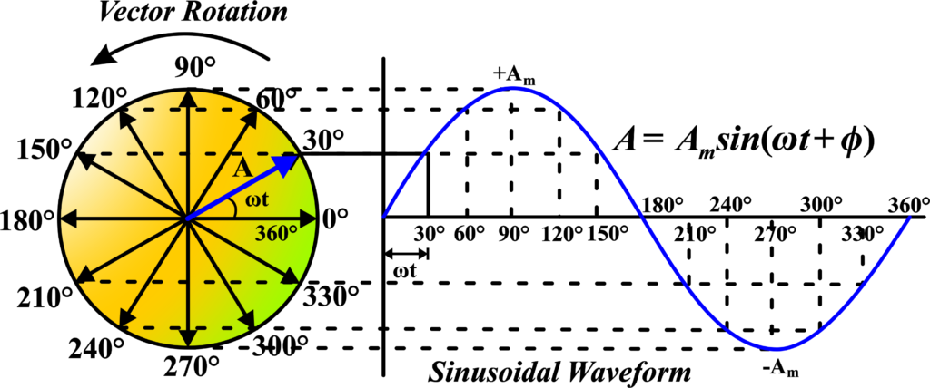
The story of phasors begins with the need to simplify the mathematics of alternating current (AC) circuits. In the late 19th century, as the use of AC for power distribution became more prevalent, engineers faced complex calculations involving trigonometric functions due to the sinusoidal nature of AC.
Enter Charles Proteus Steinmetz, a brilliant electrical engineer who worked for General Electric. Steinmetz was a pioneer in the field of electrical engineering and made numerous contributions, including the development of the concept of the phasor around the 1890s.
Steinmetz was inspired by the work of another great mind, Oliver Heaviside, who had developed operational calculus, a mathematical technique that allowed for the simplification of differential equations. Steinmetz took Heaviside’s ideas and applied them to AC circuit analysis, creating what we now call the phasor transform.
Before phasors, analyzing AC circuits required dealing with complex sine and cosine functions, which was time-consuming and error-prone. Phasors allowed engineers to convert these functions into simple geometric representations, making calculations much easier and more intuitive.
With phasors, the magnitude and phase of sinusoidal functions could be represented as vectors in a two-dimensional plane, turning a problem of calculus into one of simple geometry. This was revolutionary because it meant that engineers could now visually analyze the relationships between voltages and currents in AC circuits.
What is Phasor Representation?
A phasor is a vector that represents a sinusoidal function in terms of its magnitude and phase angle. Imagine you’re at a carnival, and there’s a giant Ferris wheel. Now, think of the Ferris wheel as a circle, and each cabin on the wheel as a point on the circle’s edge. As the wheel turns, the cabins go around in a circle, right? This is similar to how a phasor works.
A phasor is like an arrow that rotates around a central point, just like the cabins on the Ferris wheel. This arrow represents an alternating current (AC) or voltage that changes over time, like the current you get from a power outlet. The length of the arrow shows how strong the current or voltage is (its magnitude), and the direction in the arrow points shows what part of the cycle the current or voltage is in (its phase angle).
Now, why do we use phasors? Because they make it easier to understand AC circuits. Instead of using lots of complicated math with sine and cosine waves, we can use a simple picture—a phasor diagram—to show what’s happening.
In a phasor diagram, we draw our phasor arrows on a graph. The horizontal line is like the ground, and the vertical line is like a flagpole standing on the ground. If the phasor arrow points straight to the right, it’s like saying, “We’re starting!” This is our reference point, and we call it “zero degrees.”
As time passes, the phasor arrow starts rotating counterclockwise, like the hands of a clock moving backward. If the arrow points up, it’s like saying, “We’re a quarter of the way through the cycle.” This is 90 degrees. If it points left, it’s halfway, or 180 degrees. And if it points down, it’s three-quarters or 270 degrees.
When we have more than one phasor, like one for current and one for voltage, we can see how they relate to each other. If they point in the same direction, they’re “in phase,” meaning they reach their high points at the same time. If they don’t point in the same direction, one might be ahead or behind the other, which we call “leading” or “lagging.”
Phasor representation is super useful because it turns complex wave math into simple pictures. It helps us see:
- How strong currents and voltages are.
- When they reach their high and low points.
- How they work together in a circuit.
For example, if you have a circuit with a light bulb and a fan, the phasors can show you how the electricity flows to make them work. It’s a bit like seeing the gears inside a clock—you can understand how everything moves together.
Phasor Representation of AC
In AC circuits, voltage and current are sinusoidal and can be out of phase with each other, meaning their peaks occur at different times. Phasor diagrams help us visualize this relationship. On a phasor diagram, we plot phasors as arrows in a circular path. The angle between a phasor and a reference line (usually the horizontal axis) shows the phase difference. If two phasors are lined up, the quantities they represent are in phase; if not, they show how much one quantity leads or lags behind the other.
Imagine you’re at a dance party, and everyone is moving to the rhythm of the music. Now, think of the music as the electrical current in an AC circuit, and the dancers as electrons. The music changes its beat and intensity over time, just like AC changes its direction and magnitude. To keep track of everyone’s movements, we need a simple way to see who’s in sync with the music and who’s not. This is where phasors come in handy.
A phasor is a special kind of arrow that helps us keep track of two things:
- How strong the current or voltage is (that’s the length of the arrow).
- When the current or voltage reaches its peak (that’s the direction the arrow points).
We draw phasors on a graph called a phasor diagram. It’s like a snapshot of the dance floor from above. Each phasor arrow starts at the center and points outwards. The angle of the arrow shows us the timing of the peak (like the beat of the music), and the length shows us the strength (like the volume of the music).
AC is all about change. The current and voltage go up and down, like waves in the ocean. Phasors let us “freeze” these waves at a moment in time and see:
- Magnitude: How high the wave is (the strength of the current or voltage).
- Phase: When the wave hits its peak (the timing of the current or voltage).
Let’s say we have a circuit with a light bulb and a motor. The light bulb likes the current and voltage to be in step, like dancers moving together. But the motor is a bit different; it might want the current to peak a little before or after the voltage like a dancer doing a solo.
With phasors, we can draw arrows for the light bulb and motor and see how they line up. If they point in the same direction, they’re in sync. If not, we can see how much one is ahead or behind the other.
In the real world, circuits have things like resistors, capacitors, and inductors. These are like different dance moves that change how the current and voltage relate to each other. Phasors help us see these relationships clearly, without getting lost in complicated math.
For example:
- A resistor is like a steady dance move. The current and voltage phasors line up perfectly.
- A capacitor is like a move that delays the beat. The current phasor leads the voltage phasor.
- An inductor is like a move that holds back the beat. The current phasor lags behind the voltage phasor.
By looking at the phasor diagram, we can tell how the circuit will behave, just like watching dancers can tell us what the next move might be.
Phasor Diagrams
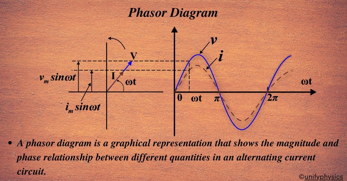
A phasor diagram is a graphical representation that shows the magnitude and phase relationship between different quantities in an alternating current circuit. It’s used to analyze the behavior of voltages and currents in AC circuits and helps in understanding the concept of phase difference and power factor.
Phasor Representation: A phasor is a vector that is used to represent a sinusoidal function. It rotates about the origin with an angular speed ω. The vertical component of phasors represents the quantities that are sinusoidally varying for a given equation, such as voltage (v) and current (i). The magnitude of the phasors represents the peak value of the voltage and the current.
Relation between Phasor and Sinusoidal Representation: The projection of the phasor on the vertical axis represents the value of the quantity. For example, in the case of a current or a voltage phasor, the projection of the phasor on the vertical axis, given by \(\displaystyle \boldsymbol{ v_m \sin\omega t}\) and \(\displaystyle\boldsymbol{ i_m \sin\omega t }\) respectively, gives the value of the current or the voltage at that instant.
Phase Difference: From the phasor diagram, it’s easy to detect that one of two quantities is in the same phase. For example, if for a given circuit, the phasors for the voltage and the current are in the same direction for all instances, the phase angle between the voltage and the current is zero.
Phasor Representation
AC current and voltage can be represented by phasors in different scenarios, including when an AC source is connected to a resistor, an inductor, or a capacitor. We will also delve into the different forms of phasor representation, namely the polar form, rectangular form, and exponential form.
Polar Form: In the polar form, a phasor is represented by its magnitude and phase angle. The magnitude is the length of the phasor, and the phase angle is the angle it makes with the positive real axis. It’s represented as \(\displaystyle A \angle \theta\), where (A) is the magnitude and θ is the phase angle.
Rectangular Form: In the rectangular form, a phasor is represented as a complex number with real and imaginary parts. The real part is the projection of the phasor on the real axis, and the imaginary part is the projection on the imaginary axis. It’s represented as (A + jB), where (A) and (B) are the real and imaginary parts respectively.
Exponential Form: In the exponential form, a phasor is represented using Euler’s formula. This form is useful for the multiplication and division of phasors. It’s represented as \(\displaystyle Ae^{j\theta}\), where (A) is the magnitude and θ is the phase angle.
Here we discuss the ‘Polar Form of a Phasor Diagram.’ In this form, we use arrows called ‘phasors’ to represent things like voltage and current on a diagram. The length of the arrow shows us how big the voltage or current can get, and the direction of the arrow tells us when it happens in the wave.
Phasor Diagram for a Resistor
Resistor: A resistor is a passive two-terminal electrical component that implements electrical resistance as a circuit element. In an AC circuit, a resistor will resist the flow of electrons, turning electrical energy into heat.
In a purely resistive AC circuit, the current and voltage are in phase with each other. This means that they reach their maximum and minimum values at the same time.
In the phasor diagram, both the voltage and the current are represented by vectors (phasors) that rotate counterclockwise. The length of the vector represents the peak value of the voltage or current. The angle between the voltage and current vectors is the phase difference.
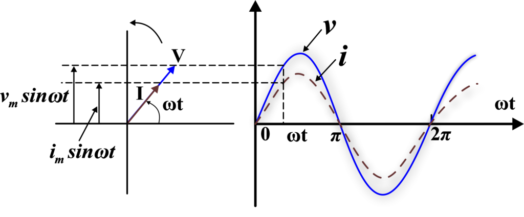
For a resistor, the voltage and current vectors are aligned, indicating that the voltage and current are in phase. This means the phase angle between the voltage and current is zero.
Representation In a purely resistive AC circuit, the current and voltage are in phase with each other. This means that they reach their maximum and minimum values at the same time. The mathematical representation for a resistor in an AC circuit is as follows:
- Voltage across the resistor: \(\displaystyle v_R = v_m \sin \omega t\)
- Current through the resistor: \(\displaystyle i_R = i_m \sin \omega t\)
Here, Im is the peak current, (R) is the resistance, and ω is the angular frequency.
Phasor Diagram for Inductor
Inductor: An inductor is a passive two-terminal electrical component that opposes sudden changes in current. It is used to store energy in the form of magnetic energy when electricity is applied to it.
In a purely inductive AC circuit, the current lags the voltage by 90 degrees. This means that the current reaches its maximum value a quarter cycle after the voltage reaches its maximum value.
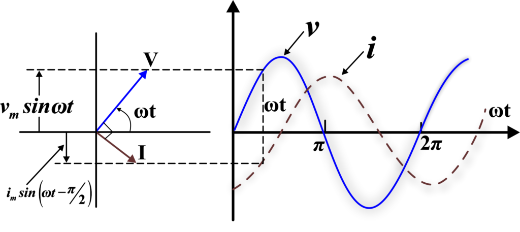
In the phasor diagram, both the voltage and the current are represented by vectors (phasors) that rotate counterclockwise. The length of the vector represents the peak value of the voltage or current. The angle between the voltage and current vectors is the phase difference.
For an inductor, the current vector is 90 degrees behind the voltage vector, indicating that the current lags the voltage by 90 degrees.
Representation: In a purely inductive AC circuit, the current lags the voltage by 90 degrees. This means that the current reaches its maximum value a quarter cycle after the voltage reaches its maximum value. The mathematical representation for an inductor in an AC circuit is as follows:
- Voltage across the inductor: \(\displaystyle v_L = v_m \sin \omega t)\)
- Current through the inductor: \(\displaystyle i_L = i_m \sin (\omega t – \frac{\pi}{2})\)
Phasor Diagram for Capacitor
Capacitor: A capacitor is a two-terminal electrical device that can store energy in the form of an electric charge. Capacitors include two electrical conductors, which are separated by a distance.
In a purely capacitive AC circuit, the current leads the voltage by 90 degrees. This means that the current reaches its maximum value a quarter cycle before the voltage reaches its maximum value.
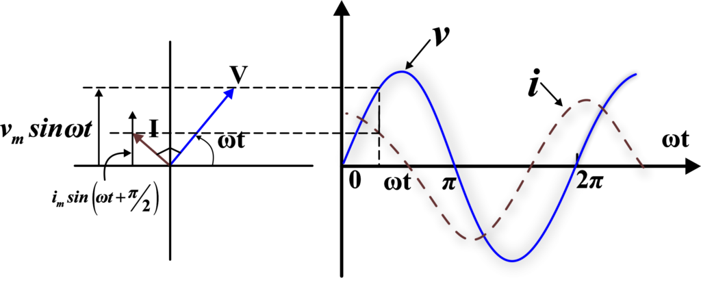
In the phasor diagram, both the voltage and the current are represented by vectors (phasors) that rotate counterclockwise. The length of the vector represents the peak value of the voltage or current. The angle between the voltage and current vectors is the phase difference.
For a capacitor, the current vector is 90 degrees ahead of the voltage vector, indicating that the current leads the voltage by 90 degrees.
Representation: In a purely capacitive AC circuit, the current leads the voltage by 90 degrees. This means that the current reaches its maximum value a quarter cycle before the voltage reaches its maximum value. The mathematical representation for a capacitor in an AC circuit is as follows:
- Voltage across the capacitor: \(\displaystyle v_C = v_m \sin \omega t)\)
- Current through the capacitor: \(\displaystyle i_C = i_m \sin (\omega t + \frac{\pi}{2})\)
Rules for Drawing a Phasor Diagram
Magnitude Representation: The length of the phasor (the vector in the diagram) corresponds to the amplitude of the wave. This means a larger amplitude wave would be represented by a longer phasor.
Direction Representation: The direction of the phasor indicates the phase of the wave. If the current is leading the voltage, the current phasor will be ahead of the voltage phasor, and vice versa.
Reference Point: The phasor diagram is drawn with respect to time zero (t = 0). This means that the position of the phasors at the start of the cycle (when time t=0) is used as the reference point for the diagram.
Rotation: The phasors rotate in a counterclockwise direction. This rotation represents the cyclic nature of the alternating current or voltage.
Phase Difference: The angle between the voltage and current vectors (phasors) in the diagram represents the phase difference between them. This angle shows how much one wave is leading or lagging behind the other.
Instantaneous Value: The projection of a phasor on the vertical axis gives the instantaneous value of the alternating quantity. This means that at any given instant, the value of the current or voltage can be determined by looking at the vertical position of the phasor.
These rules are applicable for circuits that have resistors (R), inductors (L), and capacitors (C) connected in series.
Also Read: AC Voltage Applied To A Resistor
Examples
Example 1: Given the equations \(\displaystyle I = I_0 \sin \omega t\) and \(\displaystyle E = E_0 \cos(\omega t + \pi/3)\), we need to find the phase difference between the alternating current and voltage. The phase difference is given by the difference in the angles of the sine and cosine functions. In this case, the phase difference is (\(\displaystyle\pi/3\)) radians or 60 degrees.
Solution: To find the phase difference between the alternating current and voltage, we’ll compare the angles of the sine and cosine functions.
\(\displaystyle I = I_0 \sin \omega t \)
\(\displaystyle E = E_0 \cos(\omega t + \frac{\pi}{3}) \)
The phase difference is the difference in the angles of the sine and cosine functions. In this case, the phase difference is \(\displaystyle \frac{\pi}{3} \) radians or \(\displaystyle 60^\circ \).
Therefore, the phase difference between the alternating current and voltage is \(\displaystyle \frac{\pi}{3} \) radians or \(\displaystyle 60^\circ \).
Example 2: Consider a circuit with a voltage source given by \(\displaystyle v(t) = 10 \sin(100t)\) volts and a current through the circuit given by \(\displaystyle i(t) = 5 \sin(100t + \pi/6)\) amperes. The phasor representation of the voltage is \(\displaystyle 10 \angle 0^\circ)\) and the current is \(\displaystyle 5 \angle 30^\circ)\). The phase difference between the voltage and the current is (30^\circ), which means the current leads the voltage by \(\displaystyle 30^\circ\).
Solution: In the given circuit, the voltage source is represented by the function \(\displaystyle v(t) = 10 \sin(100t)\) volts, and the current through the circuit is represented by the function \(\displaystyle i(t) = 5 \sin(100t + \pi/6)\) amperes.
The phasor representation of the voltage is \(\displaystyle 10 \angle 0^\circ\), indicating that the voltage has a magnitude of (10) units and a phase angle of \(\displaystyle 0^\circ\). Similarly, the phasor representation of the current is \(\displaystyle 5 \angle 30^\circ\), indicating a magnitude of (5) units and a phase angle of \(\displaystyle 30^\circ\).
The phase difference between the voltage and the current is \(\displaystyle 30^\circ\), which means the current leads the voltage by \(\displaystyle 30^\circ\). This phase difference can be calculated by subtracting the phase angle of the voltage from the phase angle of the current:
\(\displaystyle\text{Phase difference} = 30^\circ – 0^\circ = 30^\circ \)
Therefore, the current leads the voltage by \(\displaystyle 30^\circ\).
Example 3: Given a voltage source with \(\displaystyle v(t) = 20 \sin(50t + \pi/4)\) volts and a current \(\displaystyle i(t) = 10 \sin(50t – \pi/4)\) amperes. The phasor representation of the voltage is \(\displaystyle 20 \angle 45^\circ\) and the current is \(\displaystyle 10 \angle -45^\circ\). The phase difference between the voltage and the current is \(\displaystyle90^\circ\), which means the voltage leads the current by \(\displaystyle 90^\circ\).
Solution: In the given example, the voltage source is represented by the function \(\displaystyle v(t) = 20 \sin(50t + \frac{\pi}{4})\) volts and the current through the circuit is represented by the function \(\displaystyle i(t) = 10 \sin(50t – \frac{\pi}{4})\) amperes.
The phasor representation of the voltage is \(\displaystyle 20 \angle 45^\circ\), indicating a magnitude of (20) units and a phase angle of \(\displaystyle 45^\circ\). Similarly, the phasor representation of the current is \(\displaystyle10 \angle -45^\circ\), indicating a magnitude of (10) units and a phase angle of \(\displaystyle-45^\circ\).
The phase difference between the voltage and the current is \(\displaystyle 90^\circ\), which means the voltage leads the current by \(\displaystyle 90^\circ\). This phase difference can be calculated by subtracting the phase angle of the current from the phase angle of the voltage:
\(\displaystyle \text{Phase difference} = 45^\circ – (-45^\circ) = 90^\circ \)
Therefore, the voltage leads the current by \(\displaystyle 90^\circ\).
Example 4: Consider a circuit with a voltage source given by \(\displaystyle v(t) = 15 \sin(60t)\) volts and a current through the circuit given by \(\displaystyle i(t) = 7 \sin(60t + \pi/2)\) amperes. The phasor representation of the voltage is \(\displaystyle15 \angle 0^\circ\) and the current is \(\displaystyle7 \angle 90^\circ\). The phase difference between the voltage and the current is \(\displaystyle90^\circ\), which means the current leads the voltage by \(\displaystyle90^\circ\).
Solution: In the given example, the voltage source is represented by the function \(\displaystyle v(t) = 15 \sin(60t)\) volts, and the current through the circuit is represented by the function \(\displaystyle i(t) = 7 \sin(60t + \frac{\pi}{2})\) amperes.
The phasor representation of the voltage is \(\displaystyle 15 \angle 0^\circ\), indicating a magnitude of (15) units and a phase angle of \(\displaystyle 0^\circ\). Similarly, the phasor representation of the current is \(\displaystyle 7 \angle 90^\circ\), indicating a magnitude of (7) units and a phase angle of \(\displaystyle 90^\circ\).
The phase difference between the voltage and the current is \(\displaystyle 90^\circ\), which means the current leads the voltage by \(\displaystyle 90^\circ\). This phase difference can be calculated by subtracting the phase angle of the voltage from the phase angle of the current:
\(\displaystyle \text{Phase difference} = 90^\circ – 0^\circ = 90^\circ \)
Therefore, the current leads the voltage by \(\displaystyle 90^\circ\).
Example 5: Given a voltage source with \(\displaystyle v (t) = 25 \sin(70t + \pi/3)\) volts and a current \(\displaystyle i(t) = 12 \sin(70t)\) amperes. The phasor representation of the voltage is \(\displaystyle 25 \angle 60^\circ\) and the current is \(\displaystyle 12 \angle 0^\circ\). The phase difference between the voltage and the current is \(\displaystyle 60^\circ\), which means the voltage leads the current by \(\displaystyle 60^\circ\).
Solution: In the given example, the voltage source is represented by the function \(\displaystyle v(t) = 25 \sin(70t + \frac{\pi}{3})\) volts, and the current through the circuit is represented by the function \(\displaystyle i(t) = 12 \sin(70t)\) amperes.
The phasor representation of the voltage is \(\displaystyle 25 \angle 60^\circ\), indicating a magnitude of (25) units and a phase angle of \(\displaystyle 60^\circ\). Similarly, the phasor representation of the current is (12 \angle 0^\circ), indicating a magnitude of (12) units and a phase angle of \(\displaystyle 0^\circ\).
The phase difference between the voltage and the current is \(\displaystyle 60^\circ\), which means the voltage leads the current by \(\displaystyle 60^\circ\). This phase difference can be calculated by subtracting the phase angle of the current from the phase angle of the voltage:
\(\displaystyle \text{Phase difference} = 60^\circ – 0^\circ = 60^\circ \)
Therefore, the voltage leads the current by \(\displaystyle 60^\circ\)).
FAQs
What is a phasor diagram in the context of AC current and voltage?
A phasor diagram is a graphical representation of the magnitude and phase relationships between sinusoidal functions, such as AC current and voltage. It uses vectors (phasors) to represent the amplitude and phase of these quantities, making it easier to analyze AC circuits.
How is an AC voltage represented in a phasor diagram?
In a phasor diagram, AC voltage is represented by a rotating vector (phasor) that has a length proportional to the RMS or peak value of the voltage and an angle corresponding to its phase relative to a reference axis.
What does the angle of a phasor represent in a phasor diagram?
The angle of a phasor in a phasor diagram represents the phase angle of the sinusoidal function it depicts. This phase angle indicates the time shift between the waveform and a reference waveform, usually taken as zero degrees.
How do you represent the relationship between current and voltage in a resistor using a phasor diagram?
In a phasor diagram for a resistor, the current and voltage phasors are in phase, meaning they have the same angle and point in the same direction. This indicates that the voltage and current reach their maximum and zero values simultaneously.
How does a phasor diagram help in analyzing AC circuits with multiple components?
A phasor diagram helps in analyzing AC circuits with multiple components by visually representing the magnitude and phase relationships between voltages and currents. This makes it easier to calculate the resultant voltages and currents using vector addition and to understand how different components affect the circuit’s behavior.
What is the significance of the length of a phasor in a phasor diagram?
The length of a phasor in a phasor diagram represents the magnitude (amplitude) of the AC quantity it depicts, such as voltage or current. Longer phasors indicate higher magnitudes and shorter phasors indicate lower magnitudes.
How do you construct a phasor diagram for a simple RLC circuit?
To construct a phasor diagram for a simple RLC (resistor, inductor, capacitor) circuit, you draw phasors for the voltage drops across each component. The voltage across the resistor is in phase with the current, the voltage across the inductor leads the current by 90 degrees, and the voltage across the capacitor lags the current by 90 degrees. By adding these phasors vectorially, you can find the total voltage and current phasors for the circuit.
