The story begins in the early 19th century. Before this time, electricity and magnetism were thought to be unrelated phenomena. It was the era of scientific giants like Hans Christian Ørsted and André-Marie Ampère, who were about to uncover the deep connection between these two forces of nature.
In 1820, Ørsted discovered that a compass needle was deflected from magnetic north when an electric current from a battery was switched on and off. This simple observation demonstrated that electric currents create magnetic fields. This was groundbreaking because it linked electricity to magnetism for the first time.
Building on Ørsted’s discovery, Ampère conducted a series of experiments to understand the relationship between electricity and magnetism further. He found that two parallel wires carrying currents attract each other if the currents flow in the same direction and repel each other if they flow in opposite directions. This was the first time anyone had observed the force between current-carrying conductors.
Ampère formulated a law to describe the force between two current-carrying conductors, now known as Ampère’s Force Law. This law states that the force between two parallel conductors is proportional to the product of their currents and inversely proportional to the distance between them.
The understanding of the force between current-carrying conductors has had profound implications for modern technology. It’s the principle behind the electric motor and generator, which are the cornerstones of modern industry and technology.
Force in a Magnetic Field
Firstly, it’s important to know what a magnetic field is. Imagine a magnetic field as an invisible area around a magnet where magnetic forces can be felt. This field is strongest near the magnet and diminishes with distance. It’s similar to how you can feel the heat around a fire without touching the flames.
Now, when a charged particle, like an electron, enters this magnetic field, it experiences a force. This force is known as the Lorentz force. It’s the force that acts on particles due to electromagnetic fields, including magnetic fields. The formula for the Lorentz force is:
\(\displaystyle F = qvB \sin(\theta) \)
- (F) is the force on the particle,
- (q) is the electric charge of the particle,
- (v) is the velocity of the particle,
- (B) is the magnetic field strength,
- (θ) is the angle between the velocity and the magnetic field direction.
To determine the direction of this force, physicists use something called the right-hand rule. If you point your thumb in the direction of the particle’s velocity (v) and your fingers in the direction of the magnetic field (B), your palm will show the direction of the force for a positively charged particle. For a negatively charged particle, the force will be in the opposite direction.
When it comes to a wire carrying an electric current, which is essentially a bunch of moving charges, the wire experiences a force in a magnetic field. The direction of the force is still given by the right-hand rule, but this time you use the direction of the current instead of the velocity of a single particle.
The Force between Two Parallel Current Carrying Conductor
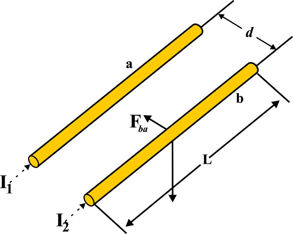
Imagine two long, straight wires running parallel to each other. When an electric current flows through these wires, they don’t just carry electricity; they also create invisible magnetic fields around them.

Each wire generates a magnetic field that extends into the space around it. When there are two wires with currents, their magnetic fields interact. If the currents are flowing in the same direction, the wires attract each other. If the currents are flowing in opposite directions, the wires repel each other.
The force between the two wires can be calculated using a formula derived from Ampère’s law. The formula is:
\(\displaystyle F = \frac{\mu_0 I_1 I_2 L}{2\pi d} \)
- (F) is the force between the wires,
- (µ0) is the magnetic constant (also known as the permeability of free space),
- (I1) and (I2) are the currents in the two wires,
- (L) is the length of the wires,
- (d) is the distance between the centers of the two wires.
To determine the direction of the magnetic fields and the resulting force, we use the right-hand rule. Point your thumb in the direction of the current, and your fingers will curl in the direction of the magnetic field. When you do this for both wires, you can see how the fields interact and whether the wires will attract or repel each other.
To make this concept easier to grasp, think of the wires like two people holding magnets. If they hold the magnets with the same poles facing each other, the magnets will push away from each other. If they hold opposite poles facing each other, the magnets will pull towards each other. The wires with currents behave similarly due to their magnetic fields.
Derivation: First, we need to understand that a current-carrying conductor generates a magnetic field around it. According to Biot-Savart Law, the magnetic field (B) at a point due to a small current element (Idl) is given by:
\(\displaystyle dB = \frac{\mu_0}{4\pi} \frac{Idl \times \hat{r}}{r^2} \)
To find the total magnetic field (B) due to the entire length of the wire, we need to integrate (dB) over the length of the wire. For a long straight wire, the magnetic field at a distance ( d ) from the wire is perpendicular to both (dl) and (\(\displaystyle\hat{r} \)), simplifying the cross product to (\(\displaystyle dl \cdot \sin(90^\circ) = dl \)).
Due to the symmetry of the problem, the magnetic field at a distance (d) from a long straight wire is the same at all points equidistant from the wire. The direction of (B) follows the right-hand rule, circling the wire.
For a long straight conductor carrying a current (I1), the magnetic field at a distance (d) from the conductor is given by Ampère’s Law:
\(\displaystyle B = \frac{\mu_0 I_1}{2\pi d} \)……..(1)
Now, let’s place a second parallel conductor at a distance (d) from the first, carrying a current (I2). The force on this second conductor due to the magnetic field created by the first conductor can be found using the Lorentz force law, which states that the force (F) on a length (L) of the conductor is:
\(\displaystyle F = I_2 L B \)
Substituting the expression for (B) from eq. (1), we get:
\(\displaystyle F = I_2 L \left( \frac{\mu_0 I_1}{2\pi d} \right) \)
To find the force per unit length between the two conductors, we divide the force by the length (L) of the conductor:
\(\displaystyle \frac{F}{L} = \frac{I_2 {L} \left( \frac{\mu_0 I_1}{2\pi d} \right)}{{L}} \)
Simplifying, we get the final expression for the force per unit length between two parallel current-carrying conductors:
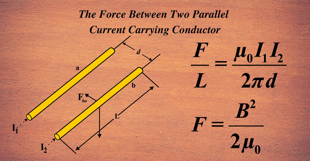
\(\displaystyle \frac{F}{L} = \frac{\mu_0 I_1 I_2}{2\pi d} \)
This expression tells us that the force per unit length is directly proportional to the product of the currents in the two conductors and inversely proportional to the distance between them. It also depends on the permeability of free space (µ0), which is a constant.
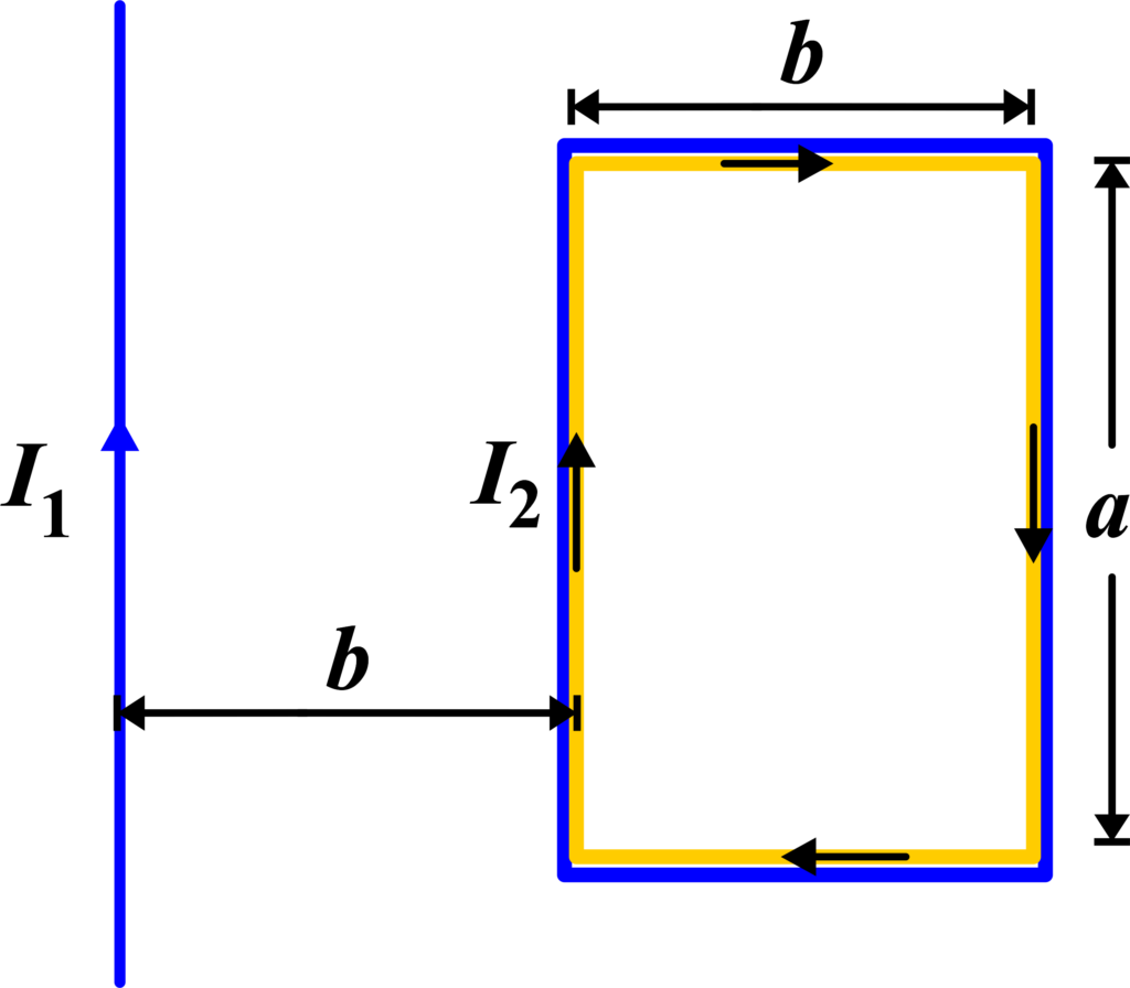
The Force between a Long Straight Conductor and A Parallel Current-Carrying Rectangular Loop
Ampère’s Law states that the line integral of the magnetic field (\(\displaystyle\vec{B}\)) around a closed loop is equal to the permeability of free space (µ0) times the current (Ienc) enclosed by the loop:
\(\displaystyle \oint \vec{B} \cdot d\vec{l} = \mu_0 I_{enc} \)

For a rectangular loop parallel to a long straight conductor carrying current (I1), the sides of the loop perpendicular to the conductor do not contribute to the line integral because (\(\displaystyle\vec{B}\)) and (\(\displaystyle d\vec{l}\)) are orthogonal. Only the sides parallel to the conductor contribute to the integral.
If the loop has sides of length (a) and (b), with (b) much larger than (a), the integral simplifies to:
\(\displaystyle B (2b) = \mu_0 I_1 \)
From the above equation, we solve for the magnetic field (B) produced by the straight conductor at the location of the loop:
\(\displaystyle B = \frac{\mu_0 I_1}{2b} \)
The force exerted by this field on a segment of length (L) of the second conductor (the rectangular loop) carrying current (I2) is given by the Lorentz force law:
\(\displaystyle F = I_2 L B \)
Substituting the expression for (B) into the force equation, we get:
\(\displaystyle F = I_2 L \left( \frac{\mu_0 I_1}{2b} \right) \)
The force per unit length between the straight conductor and the loop is then:
\(\displaystyle \frac{F}{L} = \frac{\mu_0 I_1 I_2}{2b} \)
This is the expression for the force per unit length between a long straight conductor and a parallel current-carrying rectangular loop. The direction of the force can indeed be determined using the right-hand rule.
The Force Between Two Parallel Current Carrying Sheets
Let’s start with one sheet carrying a current. This sheet creates a magnetic field around it. For simplicity, we assume that the magnetic field is uniform and only exists between the two sheets. The magnetic field due to one sheet is given as (\(\displaystyle\frac{1}{2}B\)).
When we have two sheets, the magnetic fields produced by each sheet add up between the sheets. Since the magnetic field outside the sheets is zero, we only consider the space between them. The total magnetic field (B) between the sheets is the sum of the fields due to each sheet, which is
\(\displaystyle\frac{1}{2}B + \frac{1}{2}B = B \).
The magnetic force per unit area (F/A) acting on each sheet can be found using the formula given in the reference:
\(\displaystyle F = \frac{B^2}{2\mu_0} \)
Here, (B) is the magnetic field between the sheets, and (µ0) is the permeability of free space.
To express (B) in terms of the current, we use Ampère’s Law, which relates the magnetic field around a conductor to the current it carries. For a sheet carrying a current (I) per unit width, the magnetic field due to one sheet at a point in the space between the sheets is \(\displaystyle \frac{1}{2}B\). However, to find the exact expression for (B) in terms of (I), we would need to integrate the contributions from all parts of the sheet, which is beyond the scope of this derivation.
The force between two parallel current-carrying sheets depends on the square of the magnetic field between them and inversely on the permeability of free space. This derivation shows the direct relationship between electric current and magnetic forces, a fundamental concept in electromagnetism. The above-mentioned formula is similar to F = BIl on a straight wire.
Also Read: Ampère’s Law
Solved Examples
Problem 1: A straight wire of length (0.5 m) carries a current of (4 A) and is placed in a uniform magnetic field of (0.3 T) directed perpendicular to the wire. Calculate the force acting on the wire.
Solution: The force (F) on a current-carrying wire in a magnetic field is given by:
\(\displaystyle F = I L B \sin\theta \)
Given: (I = 4 A), (L = 0.5 m), (B = 0.3 T)
\(\displaystyle F = 4 \times 0.5 \times 0.3 \times 1 \)
\(\displaystyle F = 0.6 \, \text{N} \)
The force acting on the wire is (0.6 N).
Problem 2: Two long, parallel conductors are placed 0.2 m apart and carry currents of (10 A) and (15 A) in the same direction. Calculate the force per unit length between the conductors.
Solution: The force per unit length (f) between two parallel current-carrying conductors is given by:
\(\displaystyle f = \frac{\mu_0 I_1 I_2}{2\pi d} \)
Given: (I1 = 10 A), (I2 = 15 A), (d = 0.2 m)
\(\displaystyle f = \frac{4\pi \times 10^{-7} \times 10 \times 15}{2\pi \times 0.2} \)
\(\displaystyle f = \frac{6 \times 10^{-6}}{0.2} \)
\(\displaystyle f = 3 \times 10^{-5} \, \text{N/m} \)
The force per unit length between the conductors is (\(\displaystyle 3 \times 10^{-5} \, \text{N/m} \)).
Problem 3: A long straight conductor carrying a current of (8 A) is placed parallel to a rectangular loop carrying a current of (5A). The loop has sides of (0.1 m) and (0.2 m) and is placed at a distance of (0.05 m) from the conductor. Calculate the force between the conductor and the loop.
Solution: The force between a long straight conductor and a rectangular loop can be found by calculating the forces on each side of the loop and summing them up.
Let’s calculate the force on one side of the loop parallel to the conductor. The length of the side parallel to the conductor is (L = 0.2 m). The force per unit length between the conductor and this side of the loop is:
\(\displaystyle f = \frac{\mu_0 I_1 I_2}{2\pi d} \)
\(\displaystyle f = \frac{4\pi \times 10^{-7} \times 8 \times 5}{2\pi \times 0.05} \)
\(\displaystyle f = \frac{16 \times 10^{-6}}{0.05} \)
\(\displaystyle f = 3.2 \times 10^{-4} \, \text{N/m} \)
The force on the side of length (0.2 m) is:
\(\displaystyle F_{\text{side}} = f \times L \)
\(\displaystyle F_{\text{side}} = 3.2 \times 10^{-4} \times 0.2 \)
\(\displaystyle F_{\text{side}} = 6.4 \times 10^{-5} \, \text{N} \)
Since there are two sides parallel to the conductor, the total force is:
\(\displaystyle F_{\text{total}} = 2 \times 6.4 \times 10^{-5} \)
\(\displaystyle F_{\text{total}} = 1.28 \times 10^{-4} \, \text{N} \)
The total force between the conductor and the loop is (\(\displaystyle 1.28 \times 10^{-4} \, \text{N} \)).
Problem 4: Two large, parallel sheets of current carry uniform current densities of (5 A/m) and (8 A/m) in opposite directions. They are separated by a distance of (0.1 m). Calculate the force per unit area between the sheets.
Solution: The force per unit area (f) between two parallel current-carrying sheets is given by:
\(\displaystyle f = \frac{\mu_0 J_1 J_2}{2} \)
Given: (J1 = 5 A/m}), (J2 = 8 A/m)
\(\displaystyle f = \frac{4\pi \times 10^{-7} \times 5 \times 8}{2} \)
\(\displaystyle f = \frac{4\pi \times 10^{-7} \times 40}{2} \)
\(\displaystyle f = 8\pi \times 10^{-7} \)
\(\displaystyle f \approx 2.51 \times 10^{-6} \, \text{N/m}^2 \)
The force per unit area between the sheets is (\(\displaystyle 2.51 \times 10^{-6} \, \text{N/m}^2 \)).
Problem 5: A semicircular wire of radius (0.05 m) carries a current of (2 A). It is placed in a uniform magnetic field of (0.1 T) perpendicular to the plane of the semicircle. Calculate the force on the semicircular wire.
Solution: The force on a semicircular wire in a magnetic field is given by:
\(\displaystyle F = I \cdot 2rB \)
Given: (I = 2 A), (r = 0.05 m), (B = 0.1 T)
\(\displaystyle F = 2 \times 2 \times 0.05 \times 0.1 \)
F = 0.02 N
The force on the semicircular wire is (0.02 N).
FAQs
What causes the force between two parallel current-carrying conductors?
The force between two parallel current-carrying conductors is caused by the interaction of their magnetic fields. When electric currents flow through the conductors, they generate magnetic fields around them. These magnetic fields interact, producing a force that either attracts or repels the conductors depending on the direction of the currents.
How does the direction of current in the conductors affect the force between them?
The direction of current in the conductors determines whether the force between them is attractive or repulsive. If the currents in both conductors flow in the same direction, they attract each other. If the currents flow in opposite directions, they repel each other. This is due to the interaction of the magnetic fields generated by the currents.
Why is the concept of the force between parallel current-carrying conductors important?
Understanding the force between parallel current-carrying conductors is important because it underpins the definition of the ampere, the unit of electric current in the International System of Units (SI). It also has practical applications in the design and operation of electrical devices such as motors, generators, and transmission lines.
How does the distance between two parallel conductors affect the force between them?
The distance between two parallel conductors affects the magnitude of the force between them. As the distance increases, the force decreases. This inverse relationship means that conductors placed closer together experience a stronger force, while those placed further apart experience a weaker force.
What role does the magnitude of the currents play in determining the force between two parallel conductors?
The magnitude of the currents flowing through the parallel conductors directly affects the force between them. Larger currents result in stronger magnetic fields, which in turn produce a greater force between the conductors. Conversely, smaller currents generate weaker magnetic fields and a smaller force.
Can the force between two parallel current-carrying conductors be used in practical applications? If so, how?
Yes, the force between two parallel current-carrying conductors can be used in practical applications. For example, it is utilized in the operation of electric motors, where the interaction of magnetic fields produces rotational motion. It is also important in the design of power transmission lines, where the forces between conductors must be managed to ensure stability and safety.
How is the force between two parallel current-carrying conductors measured experimentally?
The force between two parallel current-carrying conductors can be measured experimentally using a setup where the conductors are suspended in a way that allows them to move in response to the magnetic forces. By measuring the displacement or tension in the conductors and knowing the currents and distances involved, the force can be calculated. This type of experiment helps illustrate the principles of electromagnetic interactions tangibly.
