
The moving coil galvanometer is a refined version of the original galvanometer, which was an early instrument used to detect and measure electric currents. The journey of the galvanometer began with the discovery by Hans Christian Ørsted in 1820 that a magnetic compass needle deflects when it is near a wire carrying an electric current. This observation laid the foundation for the development of the galvanometer.
The term “galvanometer” was named after the Italian scientist Luigi Galvani, who, in 1791, discovered that the legs of a dead frog would twitch when struck by an electrical current. This phenomenon was termed “galvanism” and was pivotal in the study of electrophysiology.
Early galvanometers were not calibrated and could only detect the presence of current but not measure its strength accurately. André-Marie Ampère, who gave mathematical expression to Ørsted’s discovery, was instrumental in the evolution of the galvanometer.
The moving coil galvanometer, specifically, was developed as a more sensitive and precise instrument. It uses a small pivoting coil of wire within the field of a permanent magnet. When an electric current flows through the coil, it generates a magnetic field that interacts with the permanent magnet’s field, causing the coil to twist and move a pointer across a scale. This movement is proportional to the strength of the current flowing through the coil.
The D’Arsonval/Weston type, which is still in use today, represents the modern form of the galvanometer. It was designed to overcome the limitations of earlier versions, such as being affected by nearby magnets or iron masses and having a non-linear deflection relative to the current.
What Is a Moving Coil Galvanometer?
A moving coil galvanometer is an instrument that measures small electric currents. It is highly sensitive and can detect currents as low as a few microamperes.
Imagine you want to measure something very delicate, like the weight of a feather. You’d need a scale that’s sensitive enough to detect such a small weight, right? Similarly, to measure tiny electric currents, we use a moving coil galvanometer.
It’s an electromagnetic device that can measure currents even as low as a few microamperes. The “moving coil” part of its name comes from its main component—a coil of wire that moves when an electric current passes through it.
The moving coil galvanometer works on a simple principle: when an electric current flows through a coil placed in a magnetic field, it experiences a force. This force creates a torque on the coil, causing it to rotate. The amount of rotation is proportional to the current flowing through the coil. So, by measuring how much the coil turns, we can figure out the strength of the current.
The moving coil galvanometer is special because it’s incredibly sensitive and provides accurate measurements for small currents. It’s like having a high-precision tool that can pick up the slightest changes, which is crucial in experiments and electrical measurements.
Principle of Moving Coil Galvanometer
The moving coil galvanometer operates on a fundamental principle of electromagnetism. It’s all about the interaction between electricity and magnetism, which are two sides of the same coin.
When a current-carrying conductor is placed in a magnetic field, it experiences a force. If this conductor is free to move, like the coil in our galvanometer, it will start to rotate. This rotation is due to a torque acting on the coil. The principle is based on the torque that acts on a current-carrying coil placed in a magnetic field. The deflection of the coil is proportional to the current flowing through it.
In a moving coil galvanometer, the coil is suspended in a strong magnetic field. When a current passes through the coil, it creates its magnetic field. The interaction between these two fields generates a torque, causing the coil to twist. The coil is attached to a spring, which provides a counter-torque, and a pointer, which shows the deflection on a scale.
The beauty of this device lies in its proportional response: the deflection of the pointer is directly proportional to the current passing through the coil. This means that by reading the angle of deflection, we can accurately measure the current.
Think of the galvanometer as a dancer. The magnetic field is the stage, and the electric current is the music. When the music plays (current flows), the dancer (coil) performs (rotates). The more intense the music (stronger the current), the more dramatic the performance (greater the deflection).
Construction of Moving Coil Galvanometer
The moving coil galvanometer is like a delicate instrument in an orchestra, where every part has a specific role to play to create harmony.
- The Frame: At the heart of the galvanometer is a rectangular coil made up of many turns of thinly insulated copper wire. This coil is wound over a lightweight metallic frame, which is usually rectangular or circular.
- The Suspension: The coil is delicately suspended between the pole pieces of a horseshoe magnet. It hangs on a fine phosphor-bronze strip from a movable torsion head, which allows it to rotate freely.
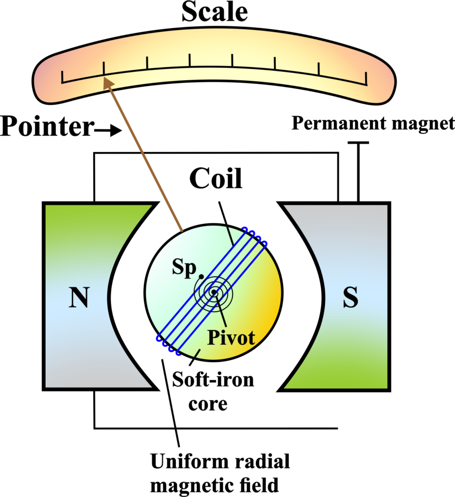
- The Core: Inside the coil, there’s a soft iron core. This isn’t just any piece of metal; it’s there to make the magnetic field as uniform as possible, ensuring that the coil experiences a consistent force no matter its position.
- The Magnetic Field: Speaking of the magnetic field, the pole pieces of the magnet are shaped in a way that creates a radial magnetic field.
This means that the magnetic field lines are always perpendicular to the coil, which is crucial for accurate measurements.
- The Pointer: Attached to the coil is a pointer, which moves over a calibrated scale. This pointer is what shows us the deflection caused by the current.
- The Springs: At the bottom of the coil, there’s a phosphor-bronze spring connected to it. This spring provides a restoring torque—a twist that brings the coil back to zero when there’s no current.
- The Mirror: To measure the deflection even more precisely, a small plane mirror is attached to the suspension wire. This is used with a lamp and scale arrangement, known as a mirror galvanometer, to measure tiny deflections without parallax error.
When all these parts come together, they form a sensitive and precise instrument that can detect even the smallest currents. In essence, the construction of the moving coil galvanometer is a fine balance of mechanical and electrical components, all working together to convert an electrical current into a measurable mechanical force.
Working of Moving Coil Galvanometer
To understand how a moving coil galvanometer works, let’s visualize it as a tiny engine that converts electrical energy into mechanical motion. Imagine a small rectangular coil made of many turns of copper wire. This coil is placed in a strong magnetic field created by a permanent magnet. The coil is free to rotate on its axis, and it’s connected to a pointer that moves over a scale.
When an electric current passes through the coil, it generates a magnetic field around it. Now, this magnetic field interacts with the magnetic field of the permanent magnet. According to Fleming’s Left-Hand Rule, a force acts on the sides of the coil that are perpendicular to the magnetic field, causing the coil to rotate.
As the coil rotates, the pointer attached to it moves over the scale. The scale is calibrated in such a way that the deflection of the pointer corresponds to the strength of the current passing through the coil.
There are springs attached to the coil that provide a restoring force. This force opposes the rotation of the coil and eventually brings it to rest at a position where the torque due to the magnetic force is balanced by the torque of the spring. This resting position of the pointer indicates the current’s magnitude.
The sensitivity of the galvanometer depends on several factors, such as the strength of the magnetic field, the number of turns in the coil, and the area of the coil. A more sensitive galvanometer can detect smaller currents.
Think of the galvanometer as a dancer on a stage (the magnetic field) with a ribbon (the coil). When music (current) plays, the dancer starts to move (the coil rotates), and the ribbon swirls around (the pointer deflects). The more intense the music, the more vigorous the dance, and the greater the swirl of the ribbon.
Simply, the moving coil galvanometer is a delicate instrument that translates the invisible electric current into a visible mechanical movement, allowing us to measure even the smallest currents with precision and ease.
Torque in a Moving Coil Galvanometer:
A moving coil galvanometer measures small electric currents by detecting the torque on a coil in a magnetic field. We have a coil with (N) turns, each of area (A). The coil carries a current (I) and is placed in a uniform magnetic field (B).
When the current flows through the coil, a magnetic force acts on it. The sides of the coil perpendicular to the magnetic field experience a force that creates a torque.
The force on each side of the coil is given by (\(\displaystyle F = B \cdot I \cdot l\)), where (l) is the length of the side of the coil.
The torque (τ) on the coil is the force times the distance from the pivot point (which is half the breadth (b) of the coil) times the number of turns:
\(\displaystyle \tau = N \cdot B \cdot I \cdot l \cdot \frac{b}{2} \)
Since the area (A) of the coil is (\(\displaystyle l \cdot b\)), we can rewrite the torque as:
\(\displaystyle \tau = N \cdot B \cdot I \cdot A \cdot \frac{1}{2} \)
The coil is attached to a spring with a spring constant (k), which provides a restoring torque that opposes the magnetic torque. At equilibrium, the magnetic torque equals the restoring torque:
\(\displaystyle N \cdot B \cdot I \cdot A \cdot \frac{1}{2} = k \cdot \theta \)
where (θ) is the angle of deflection. To find the current (I), we rearrange the equation to solve for (I):
\(\displaystyle I = \frac{k \cdot \theta}{N \cdot B \cdot A \cdot \frac{1}{2}} \)
Now, let’s simplify this. Since the (\(\displaystyle\frac{1}{2}\) ) is in the denominator, we can multiply both sides of the equation by 2 to get rid of it:
\(\displaystyle I = \frac{2 \cdot k \cdot \theta}{N \cdot B \cdot A} \)
This is the simplified expression for the current (I) in terms of the deflection angle (θ), the number of turns (N), the magnetic field strength (B), the area of the coil (A), and the spring constant (k). It shows that the current is directly proportional to the angle of deflection and inversely proportional to the other factors.
So, the simpler formula for the current (I) based on the deflection (θ) is:
\(\displaystyle I = \frac{2k\theta}{NBA} \)
This equation tells us how the current flowing through the galvanometer coil is related to the angle of deflection (θ) of the pointer on the scale.
- The current (I) is directly proportional to the angle of deflection (θ). This means that as the angle of deflection increases, the current also increases.
- The current (I) is inversely proportional to the number of turns (N), the magnetic field strength (B), and the area of the coil (A). So, if any of these factors increase, the current measured for the same deflection angle will decrease.
- Sensitivity: The spring constant (k is a measure of the galvanometer’s sensitivity. A smaller spring constant means the galvanometer is more sensitive, and a larger deflection will be observed for a given current.
What happens if we increase the number of turns in the coil?
Increasing the number of turns in the coil of a moving coil galvanometer has a direct impact on its sensitivity and performance.
Sensitivity Boost: The sensitivity of the galvanometer is proportional to the number of turns in the coil. Mathematically, the torque (τ) experienced by the coil is given by:
\(\displaystyle \tau = N \cdot B \cdot I \cdot A \)
When you increase (N), the torque increases for the same current (I), leading to a larger deflection of the pointer for the same amount of current. This makes the galvanometer more sensitive, allowing it to detect smaller currents.
Greater Precision: With more turns, the coil can produce a stronger magnetic field for a given current. This enhances the interaction with the external magnetic field, resulting in more precise measurements.
Potential Drawbacks: However, increasing the number of turns also means the coil will have a higher resistance, which can affect the circuit it’s measuring. Additionally, a larger number of turns makes the coil bulkier, which could affect its ability to rotate freely and quickly.
In practice, there’s a balance to be struck. Engineers design the coil with an optimal number of turns to ensure high sensitivity while maintaining practicality and accuracy. So, adding more turns to the coil in a moving coil galvanometer increases its sensitivity and potential for precision but must be balanced against factors like increased resistance and physical size. It’s a fine-tuning process to get the most accurate and responsive measurements possible.
The Sensitivity of Moving Coil Galvanometer
Sensitivity refers to the instrument’s ability to detect small changes in current. It is determined by the deflection per unit current.
Current Sensitivity
The current sensitivity of a moving coil galvanometer is a measure of how much the needle deflects for a given amount of current passing through the coil. It’s like having a set of highly tuned ears that can pick up the faintest sounds. It’s defined as the deflection per unit current.
Mathematically, the current sensitivity (S) of a galvanometer is defined as the deflection (θ) per unit current (I) flowing through the coil:
\(\displaystyle S = \frac{\Delta\theta}{\Delta I} \)
- (∆θ) is the change in deflection angle,
- (∆I) is the change in current.
A galvanometer with high current sensitivity will show a large deflection even for a very small current. It’s like a person who can hear a whisper in a noisy room.
Consider a galvanometer with a current sensitivity of (\(\displaystyle100 \, \text{degrees per ampere}\)). This means that for every ampere of current that flows through the coil, the pointer will deflect by 100 degrees.
To adjust the sensitivity of a galvanometer, you can change the number of turns in the coil, the strength of the magnetic field, or the area of the coil. It’s like tuning an instrument to get the perfect pitch. High current sensitivity means that even a small current will cause a large deflection, making the galvanometer suitable for detecting very small currents.
Voltage Sensitivity
Voltage sensitivity, on the other hand, is about how much the needle deflects for a given voltage applied across the coil. It’s like having a taste bud that can detect the slightest hint of sugar in a large cup of tea. It’s defined as the deflection per unit voltage.
Voltage sensitivity is the deflection of the galvanometer pointer per unit voltage applied across its terminals. Mathematically, it’s represented as:
\(\displaystyle \text{Voltage Sensitivity} = \frac{\Delta\theta}{\Delta V} \)
- (∆θ) is the change in deflection angle,
- (∆V) is the change in voltage.
The voltage sensitivity of a galvanometer can be related to its current sensitivity and the resistance of the coil. The relationship is given by:
\(\displaystyle \text{Voltage Sensitivity} = \frac{\text{Current Sensitivity}}{R} \)
where (R) is the resistance of the galvanometer coil. In simpler terms, if a galvanometer has high voltage sensitivity, it means that even a small voltage will cause a noticeable deflection of the pointer. This is crucial when measuring voltages in circuits where the current must remain as undisturbed as possible.
Imagine you’re trying to listen to a quiet song in a noisy area. If you have headphones that can amplify the song’s volume without increasing the noise, you have a situation similar to a galvanometer with high voltage sensitivity.
Just like current sensitivity, voltage sensitivity needs to be balanced. Too high sensitivity can make the galvanometer respond to unwanted signals, while too low sensitivity might not detect the required signals.
Voltage sensitivity in a moving coil galvanometer is a measure of its ability to detect small voltages. So, the sensitivities of a moving coil galvanometer tell us how responsive the instrument is to changes in current and voltage. A highly sensitive galvanometer will show large deflections for small changes, which is crucial for precise measurements in scientific experiments and electrical applications.
How does the coil’s resistance affect voltage sensitivity?
The resistance of the coil in a moving coil galvanometer plays a significant role in determining its voltage sensitivity. The voltage sensitivity (SV) of a galvanometer is the deflection per unit voltage applied across its terminals. It is given by the formula:
\(\displaystyle S_V = \frac{\Delta\theta}{\Delta V} \)
Now, the voltage (V) across the coil can be expressed using Ohm’s Law as the product of the current (I) and the resistance (R) of the coil:
\(\displaystyle V = I \cdot R \)
Therefore, the voltage sensitivity can also be related to the current sensitivity (SI) and the resistance of the coil:
\(\displaystyle S_V = \frac{S_I}{R} \)
This implies that the voltage sensitivity is inversely proportional to the resistance of the coil. However, it’s important to note that increasing the number of turns in the coil to increase current sensitivity also increases the resistance of the coil, which can affect the voltage sensitivity.
In practice, this means that if you increase the resistance of the coil, the voltage sensitivity increases because the current in the coil decreases. However, if both the current sensitivity and the resistance increase in the same order, the voltage sensitivity will remain unchanged.
To maximize voltage sensitivity, the design of the galvanometer must carefully balance the number of turns in the coil (to increase current sensitivity) and the resistance of the coil (to manage voltage sensitivity). It’s a delicate balance that ensures the galvanometer is sensitive enough to detect small voltages without becoming impractical for use due to excessive deflection for tiny currents.
Factors Affecting the Sensitivity of a Galvanometer
The sensitivity of a galvanometer is its ability to detect small currents. Think of it like a scale that can measure the lightest feather. Several factors can make this scale more or less sensitive:
Magnetic Field Strength (B): The stronger the magnetic field in which the coil is placed, the greater the force on the coil for a given current. This means the pointer will deflect more, indicating higher sensitivity.
Number of Turns in the Coil (N): More turns in the coil mean a larger magnetic effect for the same current, leading to a larger deflection and thus higher sensitivity.
Resistance of the Coil Wire (R): The resistance of the coil affects voltage sensitivity. Higher resistance with the same current sensitivity means higher voltage sensitivity, as (\(\displaystyle S_V = \frac{S_I}{R}\)).
Coupling Between Coil and Field: The alignment and interaction between the coil’s magnetic field and the external magnetic field affect the torque and thus the sensitivity. Better coupling means more deflection for the same current.
Spring Constant (k): The spring provides the restoring force that opposes the coil’s deflection. A lower spring constant means the coil can turn more easily, increasing sensitivity.
Length of the Pointer: A longer pointer will travel a greater distance across the scale for the same angular deflection, making small changes in the current more noticeable.
All these factors work together like the parts of an instrument. If one part is out of tune, it affects the overall sensitivity. By adjusting these factors, a galvanometer can be fine-tuned to measure currents with the precision needed for scientific experiments and electrical measurements.
Conversion of Galvanometer to Ammeter
An ammeter is a device used to measure larger currents in circuits, while a galvanometer is sensitive and measures only small currents. To use a galvanometer as an ammeter, we need to modify it so it can handle larger currents without getting damaged.
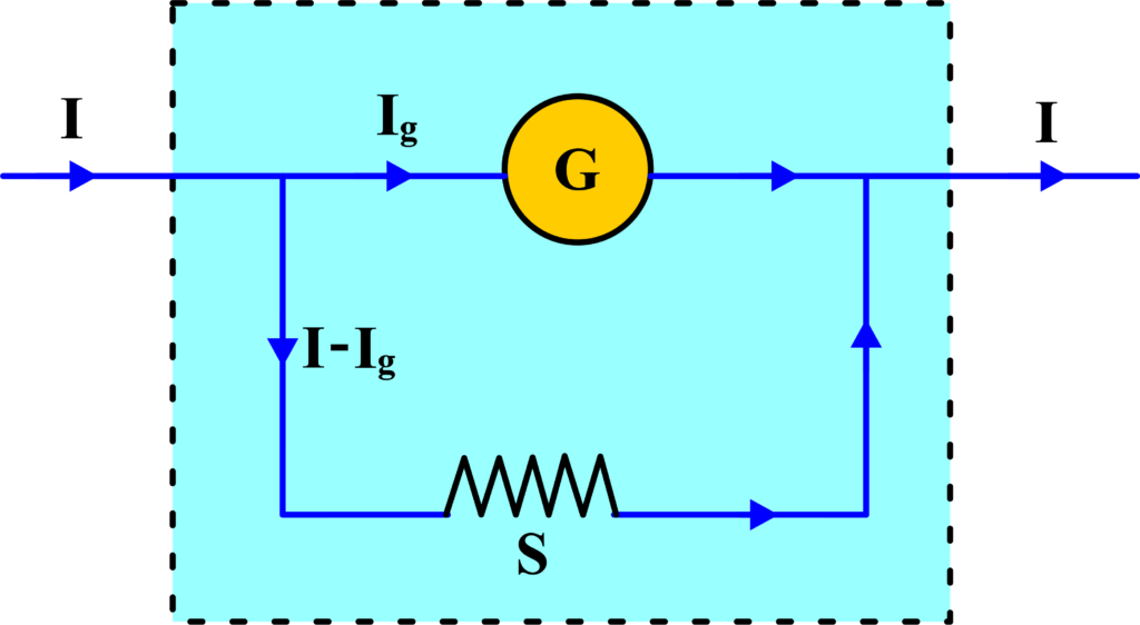
To convert a galvanometer to an ammeter, a low resistance (shunt) is connected in parallel with the galvanometer. This shunt bypasses most of the current around the galvanometer.
When connected in a circuit, the total current is divided between the shunt and the galvanometer. The majority of the current flows through the shunt due to its lower resistance.
The value of the shunt is chosen so that the maximum current we want to measure causes a full-scale deflection in the galvanometer. After adding the shunt, the scale of the galvanometer is recalibrated or replaced with a new one marked in amperes to reflect the larger currents it can now measure.
To calculate the value of the shunt resistance (S), we use the formula:
\(\displaystyle S = \frac{I_g \cdot G}{I – I_g} \)
- (Ig) is the current that gives full-scale deflection in the galvanometer,
- (G) is the resistance of the galvanometer,
- (I) is the total current we want the ammeter to measure.
Let’s say we have a galvanometer with a full-scale deflection current of (2 mA) and a resistance of (50 Ω). We want to measure up to (2 A). The shunt resistance needed would be:
\(\displaystyle S = \frac{0.002 \, \text{A} \cdot 50 \, \Omega}{2 \, \text{A} – 0.002 \, \text{A}} \approx 0.05 \, \Omega \)
By adding a shunt resistance, we effectively convert a galvanometer into an ammeter capable of measuring much larger currents. This process allows us to extend the usefulness of the sensitive galvanometer to practical applications in electrical circuits.
Shunt Resistance: A shunt is a low-resistance path that allows most of the current to bypass the galvanometer. The shunt is connected in parallel with the galvanometer.
Let ( Ig ) be the maximum current that the galvanometer can measure, which causes full-scale deflection. Let (I) be the total current we want the ammeter to measure. We need to find the value of the shunt resistance (S) that will allow the galvanometer to measure the current (I).
Using Ohm’s law, the voltage across the galvanometer (Vg) is:
\(\displaystyle V_g = I_g \cdot G \)
where (G) is the resistance of the galvanometer. Since the shunt is in parallel with the galvanometer, the voltage across the shunt (Vs) is the same as (Vg):
\(\displaystyle V_s = V_g \)
The current through the shunt (I – Ig) and the shunt resistance (S) are related by Ohm’s law:
\(\displaystyle V_s = (I – I_g) \cdot S \)
Setting (Vg) equal to (Vs), we get:
\(\displaystyle I_g \cdot G = (I – I_g) \cdot S \)
Rearranging the equation to solve for (S), we find:
\(\displaystyle S = \frac{I_g \cdot G}{I – I_g} \)
This is the expression for the shunt resistance needed to convert a galvanometer into an ammeter capable of measuring up to (I) amperes.
Conversion of Galvanometer to Voltmeter
A voltmeter is an instrument that measures the potential difference, or voltage, between two points in an electrical circuit. To measure voltage, we need a device with high resistance so that it doesn’t significantly alter the current in the circuit it’s measuring. A galvanometer, on the other hand, is sensitive and designed to measure small currents, not voltages.
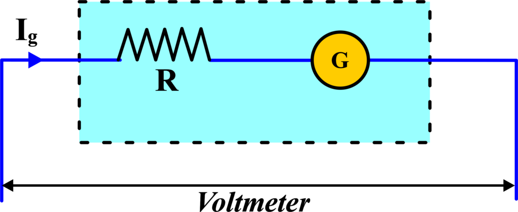
To convert a galvanometer into a voltmeter, we need to make it capable of measuring voltage without affecting the circuit. We connect a high resistance, known as a series resistor, in series with the galvanometer.
This high resistance ensures that most of the voltage from the circuit drops across it, and only a small fraction drops across the galvanometer. The galvanometer scale is then recalibrated or replaced with a new one that reads in volts instead of amperes.
The value of the series resistance (Rs) needed can be calculated using Ohm’s Law. If (V) is the maximum voltage we want to measure and (Ig) is the full-scale deflection current of the galvanometer, then:
\(\displaystyle R_s = \frac{V}{I_g} – G \)
where (G) is the resistance of the galvanometer. Let’s say we have a galvanometer with a full-scale deflection current of (50µA) and a resistance of (25 Ω). If we want to measure up to (10 V), the series resistance needed would be:
\(\displaystyle R_s = \frac{10 \, V}{50 \, \mu A} – 25 \, \Omega \approx 200 \, k\Omega \)
By adding a high series resistance to a galvanometer, we effectively convert it into a voltmeter. This allows us to measure the voltage across points in a circuit without drawing significant current through the meter itself. The galvanometer, now a voltmeter, can safely be used in various electrical measurements without affecting the circuit’s operation.
Add a High Resistance in Series: A galvanometer is a device that measures small currents. It has a coil with a resistance we’ll call (G), and it gives a full-scale deflection for a small current (Ig). Let’s say we want our voltmeter to measure up to a voltage (V). This is the maximum voltage our new voltmeter should read.
To convert the galvanometer into a voltmeter, we add a high resistance (R) in series with the galvanometer. This limits the current through the galvanometer to its full-scale deflection current (Ig), even when measuring high voltages.
Ohm’s law states that (V = I∙R ). For the full-scale deflection of the galvanometer, the current (Ig) will flow through the total resistance (R + G), where (R) is the series resistance we’ve added, and (G) is the resistance of the galvanometer.
The voltage (V) across the voltmeter (which is now our galvanometer plus the series resistance) is the current (Ig) times the total resistance (R + G):
\(\displaystyle V = I_g \cdot (R + G) \)
To find the value of (R), we rearrange the equation:
\(\displaystyle R = \frac{V}{I_g} – G \)
This is the expression for the series resistance needed to convert a galvanometer into a voltmeter that can measure up to (V) volts. By adding this resistance, we ensure that the galvanometer only allows a current (Ig) to pass through it, regardless of the voltage being measured, thus protecting it and allowing it to measure higher voltages.
Types of Moving Coil Galvanometer
Moving coil galvanometers are precise instruments used to measure small electric currents. There are mainly two types of moving coil galvanometers, each with its unique construction and use:
Suspended Coil Galvanometer: In this type, the coil is delicately suspended in the magnetic field by a thin wire or fiber. The torque on the coil, caused by the current passing through it, is balanced by the gravitational torque of the coil itself. This design allows for very sensitive measurements of current.
Pivoted Coil Galvanometer (Weston Galvanometer): The pivoted coil galvanometer, also known as the Weston galvanometer, features a coil that is pivoted on a bearing. The torque produced by the current in the coil is balanced by the spring torque of a spiral spring. This type is known for its durability and is commonly used in laboratories and industry.
These two types of moving coil galvanometers cater to different needs. The suspended coil type is used when extreme sensitivity is required, while the pivoted coil type is preferred for its robustness and ease of use in various practical applications.
Advantages of a Moving Coil Galvanometer
A moving coil galvanometer is a sensitive instrument used to detect and measure small electric currents. Here are some of its key advantages:
High Sensitivity: The moving coil galvanometer is highly sensitive, which means it can detect even very small currents. This is like having a scale that can measure the weight of a grain of sand.
Unaffected by External Magnetic Fields: It remains largely unaffected by stray magnetic fields because of its shielded design. This is similar to wearing noise-canceling headphones that block out unwanted sounds.
Accurate and Reliable: The readings of a moving coil galvanometer are reliable and accurate, making it a trusted tool in scientific experiments and electrical measurements.
High Torque-to-Weight Ratio: The design of the moving coil galvanometer ensures a high torque-to-weight ratio, which means it can produce a significant deflection for a given current without being too heavy or bulky.
Linear Scale: The scale of a moving coil galvanometer is linear, which makes reading the measurements straightforward to interpret.
The construction of the moving coil galvanometer is robust, ensuring that it can withstand regular use in a laboratory setting. It can be easily converted into an ammeter or voltmeter, making it a versatile tool for various electrical measurements.
The moving coil galvanometer is like a high-precision tool in the world of electrical measurements. Its ability to detect small currents with high accuracy and reliability makes it an indispensable instrument in physics labs and the field of electronics.
Disadvantages of a Moving Coil Galvanometer
While moving coil galvanometers have many advantages, they also come with certain limitations:
Limited to Direct Current (DC): Moving coil galvanometers can only measure direct current. They are not suitable for measuring alternating current (AC) because the direction of the current changes too quickly for the mechanism to follow.
Errors: Several factors can introduce errors in measurements,
- Aging of the Instrument: Over time, the components of the galvanometer, like its springs and magnets, can degrade, affecting accuracy.
- Damage from Mechanical Stress: If the galvanometer is dropped or handled roughly, it can damage the delicate coil or springs, leading to incorrect readings.
- Magnetic Field Variations: Changes in the magnetic field due to the aging of the magnets can cause the readings to be off.
Limited Range: Galvanometers are designed to measure small currents. For larger currents, they require modifications, like adding a shunt resistor for conversion to an ammeter.
The inertia of the Coil: The coil has mass, which means it takes time to respond to changes in current. This can make the galvanometer slow to react to rapid changes.
Temperature Sensitivity: Temperature changes can affect the metal parts of the galvanometer, causing them to expand or contract. This can alter the resistance of the coil and affect the readings.
High Sensitivity Can Be a Drawback: While high sensitivity is generally an advantage, it can also make the galvanometer respond to unintended signals or noise, leading to inaccurate readings.
Moving coil galvanometers are precise instruments, but they have their limitations. They’re best suited for measuring small, steady DC currents in a controlled environment. For other types of measurements, different instruments or additional components are needed.
Also Read: Torque on Current Loop, Magnetic Dipole
Applications of Moving Coil Galvanometer
A moving coil galvanometer is a versatile instrument in the world of physics and electronics. Here are some of its common applications:
- Measuring Small Currents: The primary use of a moving coil galvanometer is to measure small currents in circuits. It’s sensitive enough to detect currents as low as a few microamperes.
- Detecting Circuit Current Value: By connecting it in series with a low resistance, a moving coil galvanometer can help identify the value of the current flowing through a circuit.
- Measuring Voltage: When converted into a voltmeter, the moving coil galvanometer can measure the voltage across two points in a circuit.
- Making Ammeters and Voltmeters: With appropriate modifications (adding a shunt or series resistance), it can be used to create ammeters and voltmeters for larger-scale electrical measurements.
- Laboratory Experiments: In physics labs, galvanometers are used in experiments to demonstrate the principles of electromagnetism and to measure the effects of various electrical components.
- Calibration of Instruments: Moving coil galvanometers can be used to calibrate other measuring devices, ensuring their readings are accurate and reliable.
Solved Examples
Problem 1: A moving coil galvanometer has a coil resistance of (50 Ω) and shows a full-scale deflection for a current of ( 2 mA). Calculate the sensitivity of the galvanometer in terms of deflection per unit current.
Solution: The sensitivity (S) of a galvanometer is defined as the deflection per unit current:
\(\displaystyle S = \frac{\theta}{I} \)
Given: Full-scale deflection current, (\(\displaystyle I = 2 \, \text{mA} = 2 \times 10^{-3} \, \text{A} \))
Assume full-scale deflection (θ) to be (1 rad) (since the exact deflection is often considered 1 unit for full-scale).
\(\displaystyle S = \frac{1 \, \text{rad}}{2 \times 10^{-3} \, \text{A}} \)
S = 500 rad/A
The sensitivity of the galvanometer is (500 rad/A).
Problem 2: A moving coil galvanometer with a resistance of (60 Ω) gives a full-scale deflection for a current of (1 mA). It is converted into an ammeter that can read up to (10 A). Calculate the value of the shunt resistance required.
Solution: To convert a galvanometer to an ammeter, a shunt resistance (Rs) is connected in parallel with the galvanometer. The shunt resistance is given by:
\(\displaystyle R_s = \frac{I_g R_g}{I – I_g} \)
Where: \(\displaystyle I_g = 1 \, \text{mA} = 1 \times 10^{-3} \, \text{A} \)) (current for full-scale deflection); (Rg = 60 Ω) ; (I = 10 A)
\(\displaystyle R_s = \frac{1 \times 10^{-3} \times 60}{10 – 1 \times 10^{-3}} \)
\(\displaystyle R_s = \frac{60 \times 10^{-3}}{9.999} \)
\(\displaystyle R_s \approx 6 \times 10^{-3} \, \Omega \)
\(\displaystyle R_s \approx 0.006 \, \Omega \)
The shunt resistance required is approximately (0.006 Ω).
Problem 3: A moving coil galvanometer with a resistance of (75 Ω) and a full-scale deflection current of (0.5 mA) is to be converted into a voltmeter that can measure up to (10 V). Calculate the value of the series resistance required.
Solution: To convert a galvanometer to a voltmeter, a series resistance (Rs) is connected in series with the galvanometer. The series resistance is given by:
\(\displaystyle R_s = \frac{V}{I_g} – R_g \)
Where: (\(\displaystyle I_g = 0.5 \, \text{mA} = 0.5 \times 10^{-3} \, \text{A} \)); (Rg = 75 Ω) (resistance of the galvanometer); (V = 10V) (desired voltage range of the voltmeter)
\(\displaystyle R_s = \frac{10}{0.5 \times 10^{-3}} – 75 \)
\(\displaystyle R_s = \frac{10}{0.0005} – 75 \)
\(\displaystyle R_s = 20000 – 75 \)
\(\displaystyle R_s = 19925 \, \Omega \)
The series resistance required is ( 19925 Ω).
Problem 4: A galvanometer with a sensitivity of (200 rad/A) and a resistance of (100Ω) is converted into an ammeter with a shunt resistance of (0.01Ω). Calculate the new sensitivity of the ammeter in terms of deflection per unit current.
Solution: The total current (I) passing through the ammeter is the sum of the current through the galvanometer (Ig) and the current through the shunt (Is):
\(\displaystyle I = I_g + I_s \)
The new sensitivity (Snew) is given by the deflection per unit total current. Since the shunt resistance is very small, most of the current will pass through the shunt.
\(\displaystyle I_s \approx I \)
Thus, the sensitivity of the ammeter will be approximately the same as the galvanometer divided by the factor by which the shunt reduces the effective current through the galvanometer. The effective current through the galvanometer is:
\(\displaystyle I_g = \frac{I \times R_s}{R_g + R_s} \)
Given the sensitivity of the galvanometer is (Sg = 200 rad/A): The new sensitivity:
\(\displaystyle S_{\text{new}} = S_g \times \frac{I_g}{I} \)
\(\displaystyle S_{\text{new}} = 200 \times \frac{R_s}{R_g + R_s} \)
Given: Rg = 100 Ω; Rs = 0.01 Ω
\(\displaystyle S_{\text{new}} = 200 \times \frac{0.01}{100 + 0.01} \)
\(\displaystyle S_{\text{new}} = 200 \times \frac{0.01}{100.01} \)
\(\displaystyle S_{\text{new}} = 200 \times 0.0001 \)
\(\displaystyle S_{\text{new}} \approx 0.02 \, \text{rad/A} \)
The new sensitivity of the ammeter is approximately (0.02 rad/A).
Problem 5: A galvanometer with a sensitivity of (150 rad/A) and a resistance of (50Ω) is converted into a voltmeter with a series resistance of (950 Ω). Calculate the new sensitivity of the voltmeter in terms of deflection per unit voltage.
Solution: The new sensitivity (Snew) of the voltmeter is the deflection per unit voltage.
Given: Sensitivity of the galvanometer, (Sg = 150 rad/A); Rg = 50 Ω; Rs = 950 Ω.
The total resistance of the voltmeter:
\(\displaystyle R_{\text{total}} = R_g + R_s \)
\(\displaystyle R_{\text{total}} = 50 + 950 \)
\(\displaystyle R_{\text{total}} = 1000 \, \Omega \)
The new sensitivity is:
\(\displaystyle S_{\text{new}} = \frac{S_g}{R_{\text{total}}} \)
\(\displaystyle S_{\text{new}} = \frac{150}{1000} \)
\(\displaystyle S_{\text{new}} = 0.15 \, \text{rad/V} \)
The new sensitivity of the voltmeter is (0.15 rad/V).
Problem 6: A galvanometer with a resistance of ( 60Ω ) and a full-scale deflection current of (1 mA) is converted into a voltmeter with a series resistance of (5940 Ω). Calculate the full-scale voltage reading of the voltmeter.
Solution: The full-scale voltage (Vfull) of the voltmeter is given by:
\(\displaystyle V_{\text{full}} = I_g \times (R_g + R_s) \)
Where: \(\displaystyle I_g = 1 \, \text{mA} = 1 \times 10^{-3} \, \text{A} \); Rg = 60 Ω; Rs = 5940 Ω.
\(\displaystyle V_{\text{full}} = 1 \times 10^{-3} \times (60 + 5940) \)
\(\displaystyle V_{\text{full}} = 1 \times 10^{-3} \times 6000 \)
\(\displaystyle V_{\text{full}} = 6 \, \text{V} \)
The full-scale voltage reading of the voltmeter is (6 V).
FAQs
What is a moving coil galvanometer?
A moving coil galvanometer is a sensitive instrument used to detect and measure small electric currents. It operates on the principle that a current-carrying coil placed in a magnetic field experiences a torque, causing it to rotate.
How does a moving coil galvanometer work?
A moving coil galvanometer works by suspending a coil of wire between the poles of a magnet. When current passes through the coil, it experiences a torque due to the magnetic field. This torque causes the coil to rotate, and the attached pointer moves over a scale to indicate the current.
What is the role of the magnetic field in a moving coil galvanometer?
The magnetic field in a moving coil galvanometer interacts with the current flowing through the coil, generating a torque that causes the coil to rotate. This rotation is proportional to the current, allowing the device to measure the current’s magnitude.
Why are soft iron cores used in moving coil galvanometers?
Soft iron cores are used in moving coil galvanometers to enhance the magnetic field within the coil. This intensifies the interaction between the coil and the magnetic field, resulting in greater sensitivity and a more accurate measurement of small currents.
What is the significance of the damping mechanism in a moving coil galvanometer?
The damping mechanism in a moving coil galvanometer prevents oscillations of the coil, allowing it to settle quickly to a steady position. This ensures accurate and stable readings of the current without the needle fluctuating back and forth.
How can the sensitivity of a moving coil galvanometer be increased?
The sensitivity of a moving coil galvanometer can be increased by using a stronger magnetic field, increasing the number of turns in the coil, or using a coil with a larger area. These factors enhance the torque experienced by the coil for a given current, improving the device’s ability to detect small currents.
What is the difference between a moving coil galvanometer and an ammeter?
A moving coil galvanometer is primarily designed to detect and measure small currents with high sensitivity, whereas an ammeter is used to measure larger currents. A galvanometer can be converted into an ammeter by adding a low-resistance shunt in parallel with the coil, allowing it to measure higher currents without damaging the delicate coil.