The story of the transformer begins in the 19th century. The principle of electromagnetic induction, which is the science behind transformers, was discovered by Michael Faraday in 1831. However, it wasn’t until the 1880s that the first practical transformers were developed.
In the early 1880s, inventors in Hungary created what we might consider the first versions of the modern transformer. These were used in experimental and commercial systems to prove that it was possible to transfer electrical energy efficiently over long distances.
In 1885, an American inventor named William Stanley built a transformer that could be used reliably in commercial applications. His design was based on earlier work but made the transformer easier to produce and adjust for practical use.
The first time a transformer was used in a modern AC power system was in Great Barrington, Massachusetts, in 1886. This event marked the beginning of the widespread use of alternating current for electrical power distribution.
From those early days, the transformer has become an essential part of our electrical systems. It’s used everywhere, from the power lines that bring electricity to our homes to the chargers that power our phones.
What is a Transformer?
Transformers are fascinating devices that play a fundamental role in the field of electricity and power systems. They are like magical machines that can change the voltage of electricity, allowing us to efficiently transmit and use electrical energy in various applications. Understanding transformers is essential for anyone interested in how electricity works and how it powers our modern world.
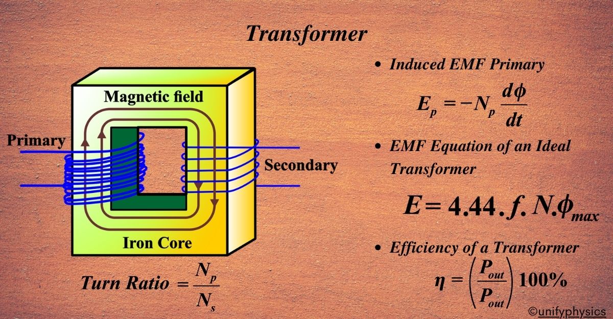
A transformer is an electrical device that ‘transforms’ the voltage of alternating current (AC) from one level to another without changing its frequency. It consists of two coils: the primary coil, which receives the input voltage, and the secondary coil, which delivers the transformed voltage.
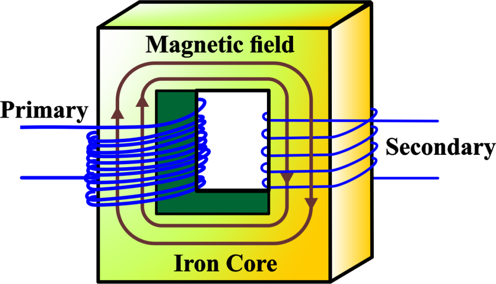
When we send electricity through the primary coil, something amazing happens. It creates a special force called a magnetic field. This magnetic field travels through the iron core and reaches the secondary coil. When this happens, it makes electricity flow in the secondary coil.
But here’s the cool part; the amount of electricity in the secondary coil depends on how many loops of wire it has compared to the primary coil. If there are more loops in the secondary coil, the electricity gets stronger. If there are fewer loops, the electricity gets weaker.
Types of Transformers
Transformers are incredible devices that come in different types, each serving a specific purpose in the world of electricity. These devices are crucial for changing the voltage of electricity to suit different applications, whether it’s transmitting power over long distances or powering electronic devices in our homes. In this article, we’ll delve into the various types of transformers, including step-up and step-down transformers, and explore how they work, their applications, and why they’re essential components of electrical systems everywhere.
Transformers come in two main types:
- Step-Up Transformer: Increases voltage from primary to secondary coil.
- Step-Down Transformer: Decreases voltage from primary to secondary coil.
Step-Up Transformer
A step-up transformer is a device that increases the voltage from the primary coil to the secondary coil. It’s like a voltage ladder, allowing electrical energy to ‘step up’ to higher levels.
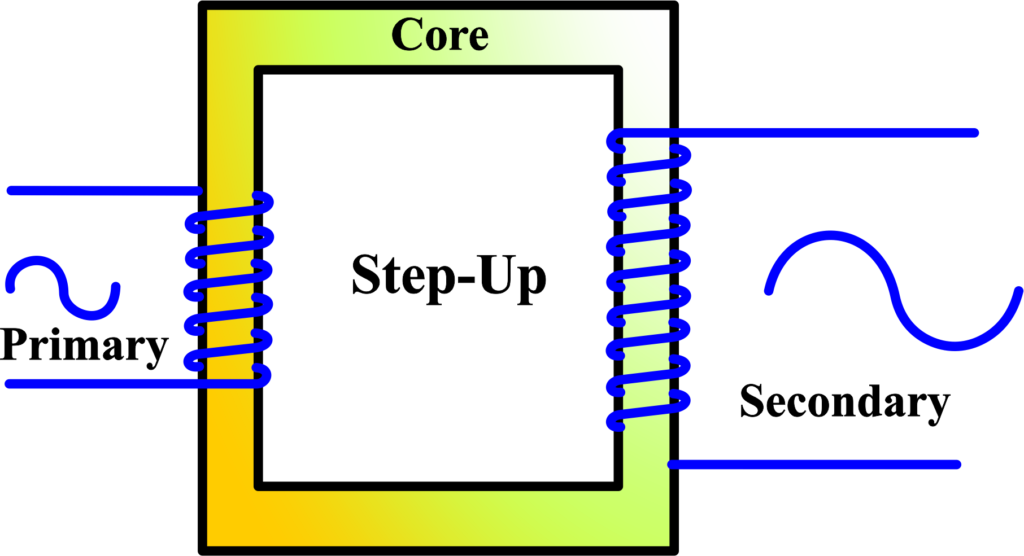
Imagine you have two coils: one with a few turns of wire (the primary) and one with many turns of wire (the secondary). When alternating current flows through the primary coil, it creates a magnetic field that envelops both coils.
Due to electromagnetic induction, this changing magnetic field induces a higher voltage in the secondary coil because it has more turns of wire.
The key to a step-up transformer’s ability to increase voltage lies in the turn ratio—the number of turns in the secondary coil compared to the primary. The voltage will be doubled if the secondary coil has twice as many turns as the primary. This ratio determines how much the voltage will be ‘stepped up’. Step-up transformers are essential in power transmission. By increasing the voltage and consequently decreasing the current, they reduce energy loss over long distances. This is because lower current means less heat generated in the power lines, making the system more efficient.
The relationship between the primary voltage (Vp), secondary voltage (Vs), primary turns (Np), and secondary turns (Ns) is given by the transformer equation:
\(\displaystyle \frac{V_s}{V_p} = \frac{N_s}{N_p} \)
A transformer works on the principle of electromagnetic induction. When an alternating current flows through the primary coil, it creates a changing magnetic field around it. This changing magnetic field induces an electromotive force (EMF) in the secondary coil due to Faraday’s law of electromagnetic induction.
Faraday’s law states that the induced EMF in a coil is equal to the negative change in magnetic flux (Φ) times the number of turns (N) in the coil:
\(\displaystyle \text{EMF} = -N \frac{d\Phi}{dt} \)
In a transformer: The primary coil has (Np) turns and a voltage (Vp). The secondary coil has ( Ns) turns and a voltage (Vs).
Assuming an ideal transformer (with no energy losses), the magnetic flux change through both coils is the same because they are wound around the same core.
Primary Coil: For the primary coil, the induced EMF (Ep) is proportional to the product of the number of turns and the rate of change of magnetic flux:
\(\displaystyle E_p = -N_p \frac{d\Phi}{dt} \)
Since we’re considering magnitudes and not the direction of the induced EMF, we can ignore the negative sign. The primary voltage ( Vp) is essentially the induced EMF ( Ep):
\(\displaystyle V_p = N_p \frac{d\Phi}{dt} \)
Secondary Coil: Similarly, for the secondary coil;
\(\displaystyle V_s = N_s \frac{d\Phi}{dt} \)
By equating the rate of change of magnetic flux through both coils, we get:
\(\displaystyle \frac{V_s}{N_s} = \frac{V_p}{N_p} \)
Rearranging the terms gives us the transformer equation:
\(\displaystyle\begin{equation}\label{eqn:4}\boxed{\boldsymbol{\frac{V_s}{V_p} = \frac{N_s}{N_p} }} \end{equation}\)
This equation shows that the voltage is directly proportional to the number of turns in the coils. This equation shows that the ratio of the secondary voltage to the primary voltage is equal to the ratio of the number of turns in the secondary coil to the number of turns in the primary coil.
The transformer equation is a direct consequence of Faraday’s law of electromagnetic induction and the assumption that the magnetic flux through both coils of the transformer is the same. It’s a fundamental concept that explains how transformers can step up or step down voltages in electrical circuits.
In practical applications, step-up transformers are used in power plants to elevate the voltage of generated electricity before it’s transmitted across power lines to cities and towns. Other transformers then step down this high voltage before it enters our homes.
Step-Down Transformers
A step-down transformer is a type of transformer that reduces high voltage from the primary coil to a lower voltage in the secondary coil. It’s like a staircase where electrical energy ‘steps down’ to a level that’s safe and usable for our appliances.
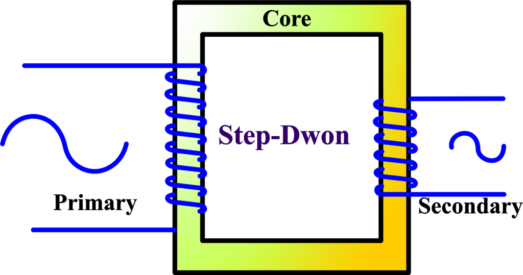
The step-down transformer operates on the principle of electromagnetic induction. When alternating current flows through the primary coil, it generates a magnetic field. This field induces a current in the secondary coil, which has fewer turns of wire than the primary.
Because of this difference in turns, the voltage is reduced. The core of the transformer is made of iron or another ferromagnetic material, which helps to efficiently transfer the magnetic field from the primary to the secondary coil. The induced voltage in the secondary coil is proportional to the number of turns in the coil. Fewer turns mean less induced voltage.
Step-down transformers are crucial in our electrical grid. They take the high-voltage electricity transmitted over long distances and reduce it to a lower voltage that can be used in homes and businesses. Without them, the electricity that powers our lives would be too dangerous to use directly from the transmission lines. You’ll find step-down transformers in various places, from the green utility boxes in neighborhoods to the power adapters for laptops and smartphones. They are an invisible yet essential part of our daily electrical usage.
Also Read: Resonance
Working Principle of a Transformer
The working principle of a transformer is based on Faraday’s law of electromagnetic induction. When an AC flows through the primary coil, it creates a changing magnetic field. This field induces an electromotive force (EMF) in the secondary coil, thus transferring energy from the primary to the secondary coil. Transformers are devices that transfer electrical energy between two or more circuits through electromagnetic induction.
The core operation of a transformer is based on the principle of electromagnetic induction, which was discovered by Michael Faraday. This principle states that a changing magnetic field within a coil of wire induces a voltage across the ends of the coil.
Mutual induction is the specific type of electromagnetic induction that transformers rely on. It occurs when a changing magnetic field in one coil induces a voltage in a neighboring coil.
The Primary Coil: The Initiator – When alternating current (AC) flows through the primary coil of a transformer, it creates a changing magnetic field around it. This magnetic field is not static; it grows and diminishes with the alternating current, which is crucial for inducing voltage in the secondary coil.
The Iron Core: The Conductor – The coils are wound around an iron core, which serves to concentrate the magnetic field and improve the efficiency of the transformer. The iron core provides a low-resistance path for the magnetic field, allowing it to easily transfer from the primary to the secondary coil.
The Secondary Coil: The Receiver – The secondary coil, which is close to the primary coil but not electrically connected, feels this changing magnetic field. According to Faraday’s law, the changing magnetic field induces an electromotive force (EMF) in the secondary coil.
Depending on the number of turns in the secondary coil relative to the primary, the induced voltage can be greater (step-up transformer) or lesser (step-down transformer) than the voltage in the primary coil. This is where the magic of voltage transformation happens.
EMF Equation of An Ideal Transformer
An ideal transformer is a theoretical transformer that has no energy losses and perfectly efficient electromagnetic induction between its coils. In reality, all transformers have some losses, but the ideal transformer concept helps us understand the basic principles without the complication of inefficiencies.
The EMF equation for an ideal transformer is derived from Faraday’s law of electromagnetic induction, which states that a change in magnetic flux through a coil will induce an EMF in the coil. The equation is:
\(\displaystyle E = 4.44 \cdot f \cdot N \cdot \Phi_{max} \)
Faraday’s law tells us that a changing magnetic field within a coil of wire induces an electromotive force (EMF) in the coil. The induced EMF (E) in a coil is directly proportional to the rate of change of magnetic flux (Φ) and the number of turns (N) in the coil:
\(\displaystyle E = -N \frac{d\Phi}{dt} \)
In a transformer, the AC current produces a magnetic flux that changes sinusoidally with time. If \(\displaystyle Φmax \) is the maximum magnetic flux, the flux at any time (t) can be expressed as:
\(\displaystyle \Phi(t) = \Phi_{max} \sin(2\pi f t) \)
The induced EMF at any time (t) is the derivative of the magnetic flux with respect to time. So, we differentiate Φ(t) with respect to (t):
\(\displaystyle \frac{d\Phi}{dt} = 2\pi f \Phi_{max} \cos(2\pi f t) \)
The maximum rate of change of flux occurs when \(\displaystyle \cos(2\pi f t) = 1 \), which gives us:
\(\displaystyle \Bigg|\frac{d\phi}{dt}\Bigg|_{\text{max}} = 2\pi f \phi{\text{max}}\)
The peak EMF (Emax) is then:
\(\displaystyle {{E}_{{\max }}}=N{{\Bigg| {\frac{{d\phi }}{{dt}}} \Bigg|}_{{\max }}}=N.2\pi f{{\phi }_{{\max }}}\)
However, we often use the root mean square (RMS) value of EMF in AC circuits, which is \(\displaystyle\frac{E_{max}}{\sqrt{2}}\). To convert the peak EMF to RMS, we divide by \(\displaystyle \sqrt{2} \) and introduce the constant (4.44), which accounts for the shape of the sine wave since \(\displaystyle \frac{2\pi}{\sqrt{2}} \approx 4.44 \):
\(\displaystyle E_{RMS} = \frac{E_{max}}{\sqrt{2}} = \frac{N \cdot 2\pi f \Phi_{max}}{\sqrt{2}} \approx 4.44 \cdot f \cdot N \cdot \Phi_{max} \)
So, the RMS value of the induced EMF in an ideal transformer is given by:
\(\displaystyle\begin{equation}\label{eqn:3}\boxed{\boldsymbol{ E = 4.44 \cdot f \cdot N \cdot \Phi_{max} }} \end{equation}\)
The EMF equation is fundamental for designing transformers. It tells us that to increase the induced EMF, we can either increase the number of turns in the coil or increase the magnetic flux. This equation also helps in calculating the efficiency and performance of a transformer. For an ideal transformer under no-load conditions, the primary EMF (E1) equals the supply voltage on the primary winding, and the secondary EMF (E2) equals the terminal voltage on the secondary winding.
Efficiency of a Transformer
Efficiency is a measure of how well a device converts input energy into useful output energy. In the case of transformers, which are used to step up or step down voltages, efficiency is crucial because it determines how much electrical power is lost in the process of voltage transformation.
The efficiency (η) of a transformer is defined as the ratio of the power output (Pout) to the power input (Pin):
\(\displaystyle\begin{equation}\label{eqn:1}\boxed{\boldsymbol{ \eta = \left( \frac{P_{out}}{P_{in}} \right) \times 100\%}} \end{equation}\)
In an ideal transformer, this ratio would be 100%, meaning no power is lost. However, all real transformers have some losses, so their efficiency is always less than 100%.
The type of iron used in the core and the insulation of the coils can affect efficiency. Better materials result in lower losses. The transformer’s design, including the number of turns in the coils and the shape of the core, can optimize efficiency. Transformers operate most efficiently at a specific load. Deviations from this load can increase losses. High efficiency is essential for transformers because it means less energy is wasted, which is both economically and environmentally beneficial. Efficient transformers reduce operating costs and help conserve resources.
Energy Losses in a Transformer
Transformers are incredibly efficient devices, but they do experience some energy losses during operation. Understanding these losses is important for students studying physics. Let’s explore the four main types of energy losses in transformers.
- Flux Leakage: Flux leakage occurs when some of the magnetic field lines generated by the primary coil don’t make it to the secondary coil. Instead, they ‘leak’ out into the surrounding space. This means not all the magnetic field contributes to inducing voltage in the secondary coil, leading to a loss of efficiency. To minimize flux leakage, transformers are designed with a closed-core structure that guides the magnetic field lines more effectively.
- Winding Resistance: Winding resistance refers to the natural resistance to current flow found in the copper or aluminum wires used for the transformer coils. As current flows through these wires, some energy is lost as heat due to this resistance. To reduce winding resistance, thicker wires with a larger cross-sectional area can be used, which allows more current to pass through with less resistance.
- Eddy Currents: Eddy currents are loops of electrical current induced within the conductive core of the transformer by the changing magnetic field. These currents flow in directions that create their own magnetic fields, opposing the original change in flux. Eddy currents result in energy being dissipated as heat within the core material. To minimize eddy currents, the core is made from laminated sheets of steel, which restrict the flow of these currents.
- Hysteresis Loss: Hysteresis loss is the energy lost due to the lagging of the magnetic field strength behind the magnetizing force. This happens because the magnetic domains in the core material take time to align with the changing magnetic field. Each time the magnetic field changes direction (which happens twice per cycle in an AC transformer), energy is lost in the form of heat. Using materials with low hysteresis, like silicon steel, can reduce these losses.
Voltage Transformation Ratio or Turn Ratio
When studying transformers in physics, two key concepts are the Voltage Transformation Ratio and the Turn Ratio. These are essential for understanding how transformers can change the voltage levels of electrical energy.
Voltage Transformation Ratio (K)
The Voltage Transformation Ratio, often denoted by (K), is the ratio of the secondary voltage (Vs) to the primary voltage (Vp). It tells us how much the voltage is increased or decreased by the transformer:
\(\displaystyle K = \frac{V_s}{V_p} \)
If (K > 1), the transformer is a step-up transformer, increasing voltage. If (K < 1), it’s a step-down transformer, decreasing voltage.
Turn Ratio
The Turn Ratio is the ratio of the number of turns in the primary coil (Np) to the number of turns in the secondary coil (Ns). It directly affects the Voltage Transformation Ratio:
\(\displaystyle \text{Turn Ratio} = \frac{N_p}{N_s} \)
At no load, the voltage ratio is equal to the turn ratio. This means that if the primary coil has 100 turns and the secondary has 50 turns, the turn ratio is 2:1, indicating a step-down transformer. The Turn Ratio and the Voltage Transformation Ratio are related because the induced voltage in a coil is proportional to the number of turns in that coil. So, if a transformer has twice as many turns in the secondary coil as in the primary coil, the secondary voltage will be twice the primary voltage, assuming no losses.
Application of Transformer
- Transformers are a cornerstone of modern electrical engineering, and their applications are vast and varied. Here are applications of transformers,
- Transformers are used in power plants to step up the voltage for efficient transmission over long distances. At the distribution end, they step down the voltage for safe residential or commercial use.
- In devices like TVs, refrigerators, and air conditioners, transformers regulate voltage to protect sensitive electronic components and ensure they operate under optimal conditions.
- Isolation transformers prevent the flow of direct current (DC) from one circuit to another and also isolate two electric circuits, which is crucial for safety and noise reduction.
- In industries, transformers are used for processes like electrolysis and electroplating, where a regulated flow of current is essential. They also provide the high currents needed for steel manufacturing and welding.
- Step-up transformers are used in medical devices, such as X-ray machines, to produce the high voltages required for imaging.
- Audio transformers match impedances between different components in audio systems, ensuring sound quality and preventing interference.
These applications show how transformers play a vital role in not only powering our homes and industries but also in ensuring the functionality and safety of various devices and systems we rely on daily.
Solved Examples
Problem 1: A transformer has 1000 turns in the primary coil and 200 turns in the secondary coil. The primary voltage is 220 V and the frequency of the supply is 50 Hz. Calculate the EMF induced in the secondary coil.
Solution:
- Number of turns in the primary coil (Np) = 1000
- Number of turns in the secondary coil (Ns) = 200
- Primary voltage (Vp) = 220 V
- Frequency (f) = 50 Hz
The EMF equation for an ideal transformer is:
\(\displaystyle V_s = V_p \times \frac{N_s}{N_p} \)
\(\displaystyle V_s = 220 \times \frac{200}{1000} \)
\(\displaystyle V_s = 220 \times 0.2 = 44 \, V \)
The EMF induced in the secondary coil is 44 V.
Problem 2: A step-down transformer has a primary voltage of 480 V and a secondary voltage of 120 V. If the secondary coil has 50 turns, calculate the number of turns in the primary coil.
Solution:
- Primary voltage (Vp) = 480 V
- Secondary voltage (Vs) = 120 V
- Number of turns in the secondary coil (Ns) = 50
Using the voltage transformation ratio:
\(\displaystyle \frac{V_p}{V_s} = \frac{N_p}{N_s} \)
\(\displaystyle \frac{480}{120} = \frac{N_p}{50} \)
\(\displaystyle 4 = \frac{N_p}{50} \)
\(\displaystyle N_p = 4 \times 50 = 200 \)
The number of turns in the primary coil is 200.
Problem 3: A transformer has an input power of 1500 W and an output power of 1350 W. Calculate the efficiency of the transformer.
Solution:
- Input power (Pin) = 1500 W
- Output power (Pout) = 1350 W
Efficiency (η) is given by:
\(\displaystyle \eta = \frac{P_{out}}{P_{in}} \times 100\% \)
\(\displaystyle \eta = \frac{1350}{1500} \times 100\% \)
\(\displaystyle \eta = 0.9 \times 100\% = 90\% \)
The efficiency of the transformer is 90%.
Problem 4: A transformer has a primary voltage of 400 V and a secondary voltage of 100 V. If the primary current is 2 A, calculate the secondary current assuming the transformer is ideal.
Solution:
- Primary voltage (Vp) = 400 V
- Secondary voltage (Vs) = 100 V
- Primary current (Ip) = 2 A
Using the current transformation ratio:
\(\displaystyle \frac{V_p}{V_s} = \frac{I_s}{I_p} \)
\(\displaystyle \frac{400}{100} = \frac{I_s}{2} \)
\(\displaystyle 4 = \frac{I_s}{2} \)
\(\displaystyle I_s = 4 \times 2 = 8 \, A \)
The secondary current is 8 A.
Problem 5: An ideal transformer has a primary voltage of 600 V and a primary current of 3 A. If the secondary voltage is 120 V, calculate the secondary current and the power handled by the transformer.
Solution:
- Primary voltage (Vp) = 600 V
- Primary current (Ip) = 3 A
- Secondary voltage (Vs) = 120 V
First, calculate the primary power:
\(\displaystyle P_p = V_p \times I_p \)
\(\displaystyle P_p = 600 \times 3 = 1800 \, W \)
Since it is an ideal transformer, the power handled by the secondary coil is the same:
\(\displaystyle P_s = 1800 \, W\)
Next, calculate the secondary current (Is):
\(\displaystyle P_s = V_s \times I_s \)
\(\displaystyle 1800 = 120 \times I_s \)
\(\displaystyle I_s = \frac{1800}{120} = 15 \, A \)
The secondary current is 15 A, and the power handled by the transformer is 1800 W.
Problem 6: A transformer has a no-load secondary voltage of 230 V and a full-load secondary voltage of 220 V. If the load connected to the secondary coil is 50 Ω, calculate the load current and the voltage regulation of the transformer.
Solution:
- No-load secondary voltage (Vnl) = 230 V
- Full-load secondary voltage (Vfl) = 220 V
- Load resistance (RL) = 50 Ω
First, calculate the load current (IL):
\(\displaystyle I_L = \frac{V_{fl}}{R_L} \)
\(\displaystyle I_L = \frac{220}{50} = 4.4 \, A \)
Next, calculate the voltage regulation:
\(\displaystyle \text{Voltage Regulation} = \frac{V_{nl} – V_{fl}}{V_{fl}} \times 100\% \)
\(\displaystyle \text{Voltage Regulation} = \frac{230 – 220}{220} \times 100\% \)
\(\displaystyle \text{Voltage Regulation} = \frac{10}{220} \times 100\% \)
\(\displaystyle \text{Voltage Regulation} \approx 4.55\% \)
The load current is 4.4 A, and the voltage regulation of the transformer is approximately 4.55%.
FAQs
What is a transformer?
A transformer is an electrical device that consists of two or more coils of wire (known as windings) that are linked by a magnetic field. It is used to transfer electrical energy from one circuit to another through electromagnetic induction.
What factors affect the efficiency of a transformer?
The efficiency of a transformer is influenced by factors such as the quality of the magnetic core, the resistance of the windings, and the frequency of the alternating current. Higher-quality materials and design contribute to higher efficiency, while factors like core losses and copper losses can reduce efficiency. Regular maintenance and proper cooling also play a role in maintaining efficiency over time.
How does a step-up transformer work?
A step-up transformer operates on the principle of electromagnetic induction. When an alternating current flows through the primary coil, it creates a changing magnetic field, which induces a voltage in the secondary coil due to mutual induction. Since the secondary coil has more turns than the primary coil, the induced voltage in the secondary coil is higher than the input voltage.
What are the applications of a step-up transformer?
Step-up transformers are commonly used in power transmission systems to increase the voltage of electricity generated at power plants before it is transmitted over long distances through power lines. They are also used in voltage regulators, cathode ray tubes (CRTs), and some types of electronic devices.
How does a step-down transformer work?
Similar to a step-up transformer, a step-down transformer operates on the principle of electromagnetic induction. When an alternating current flows through the primary coil, it creates a changing magnetic field, which induces a voltage in the secondary coil due to mutual induction. However, since the secondary coil has fewer turns than the primary coil, the induced voltage in the secondary coil is lower than the input voltage.